Chapter 5
149
Jumper and Connector Locations
Top View
Item
Description
Item
Description
J56
Subwoofer Connector
JP47
Touch pad Connector
SW1
Power button
JP33
VR board Connector
JP7
Backlight on/off Connector
JP54
Digital MIC Connector
JLVDS
Speaker (Right) Connector
SW2
Touch pad lock button
JP2
Launch board Connector
JP3
board to board Connector
JP34
Keyboard backlight Connector
JP37
Blue tooth Connector
JEXP1
New (Express) card Connector
JP44
Finger Print Connector
JKB1
Keyboard Connector
LED11
HDD_LED
JP38
POWER SAVING Connector
LED10
NUM_LED
JP48
USB cable Connector
LED9
CAPS_LED
JP55
Speaker Connector
LED1
PWR_LED
JP6
Media board Connector
LED6
Battery charger_LED
JP39
LOGO Backlight Connector
LED16
Touch pad lock_LED
Chapter 5
Содержание Aspire 5935 Series
Страница 6: ...VI ...
Страница 10: ...X Table of Contents ...
Страница 14: ...4 Chapter 1 System Block Diagram ...
Страница 47: ...Chapter 2 37 ...
Страница 54: ...44 Chapter 2 ...
Страница 81: ...Chapter 3 71 5 Using both hands lift the Speaker Module upward to remove it from the Upper Cover ...
Страница 83: ...Chapter 3 73 5 Disconnect the cable from the Power Saving Board as shown ...
Страница 88: ...78 Chapter 3 8 Remove the FInger Print Reader from the bracket as shown ...
Страница 98: ...88 Chapter 3 4 Lift the right side Saddle clear of the Lower Cover as shown ...
Страница 102: ...92 Chapter 3 5 Disconnect the cable from the Bluetooth Module ...
Страница 109: ...Chapter 3 99 5 Using both hands lift the Thermal Module clear of the Mainboard ...
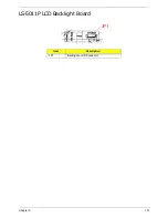
Страница 161: ...Chapter 5 151 LS 5011P LCD Backlight Board Item Description JP1 Backlight on off Connector ...
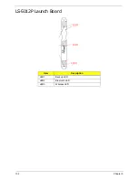
Страница 162: ...152 Chapter 5 LS 5012P Launch Board Item Description LED1 Backup LED LED2 Bluetooth LED LED3 Wireless LED ...
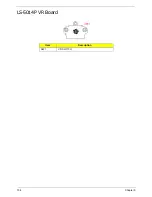
Страница 164: ...154 Chapter 5 LS 5014P VR Board Item Description SW1 VR SWITCH ...
Страница 165: ...Chapter 5 155 LS 5015P Finger printer Board Item Description U2 LTT SS801U 13_LGA28 ...
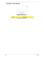
Страница 170: ...160 Chapter 5 LS 501AP HDMI Board Item Description U1 CH7318A BF TR_QFN48_7X7 ...
Страница 175: ...Chapter 6 165 Base Assembly No Description Acer P N 1 HDD Memory Door 2 WLAN Door 3 Lower Cover 1 2 3 ...
Страница 183: ...Chapter 6 173 ...
Страница 212: ...Appendix A 202 ...
Страница 218: ...208 Appendix B ...
Страница 220: ...210 Appendix C ...
Страница 224: ...214 ...

