


VIII
Table of Contents
LCD Module Disassembly Flowchart 64
Removing the LCD Bezel 65
Removing the LCD panel with the Brackets 66
Removing the LCD Brackets 70
Removing the FPC Cable 71
Removing the Web Camera 72
Removing the Microphone 74
Removing the Antennas 74
Troubleshooting 77
System Check Procedures 78
External Diskette Drive Check 78
External Optical Disk Drive Check 78
Keyboard or Auxiliary Input Device Check 78
Memory Check 79
Power System Check 79
Touchpad Check 80
Power-On Self-Test (POST) Error Message 80
Index of Error Messages 81
Phoenix BIOS Beep Codes 85
Index of Symptom-to-FRU Error Message 89
Intermittent Problems 92
Undetermined Problems 92
Main Board 93
Connector Locations 93
Clearing Password Check and BIOS Recovery 96
Clearing Password Check 96
BIOS Recovery by Crisis Disk 97
FRU (Field Replaceable Unit) List 99
Exploded Diagram 100
113
Model Definition and Configuration 113
Aspire 4750/4750G Series 114
Test Compatible Components 135
Hardware Device Tests 136
Online Support Information 139
Index 141
Содержание Aspire 4350
Страница 6: ...VI ...
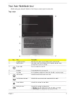
Страница 16: ...8 Chapter 1 5 USB 2 0 port Connect to USB 2 0 devices e g USB mouse USB camera Icon Item Description ...
Страница 26: ...18 Chapter 1 ...
Страница 40: ...32 Chapter 2 ...
Страница 76: ...68 Chapter 3 16 Detach the webcam cable from the webcam module 17 Disconnect the microphone cable ...
Страница 77: ...Chapter 3 69 18 Release the LCD cable from the tape 19 Remove the LCD panel with brackets from the back cover ...
Страница 84: ...76 Chapter 3 ...
Страница 106: ...98 Chapter 5 ...
Страница 108: ...100 Chapter 6 Exploded Diagram ...
Страница 109: ...Chapter 6 101 ...
Страница 121: ...Appendix A 113 Model Definition and Configuration Appendix A ...
Страница 146: ...138 Appendix B ...
Страница 148: ...140 Appendix C ...