


Chapter 3
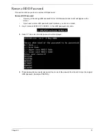
43
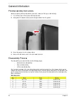
Main Unit Disassembly Process
Main Unit Disassembly Flowchart
Item
Screw
Color
Part No.
A
M2.5 x L6
Black
86.00E12.536
C
M2 x L3
Black
86.00F80.723
MAIN
UNIT
KEYBOARD
MAIN UNIT DISASSEMBLY
CPU
SCREW X 5
RTC
BATTERY
A x 10
UPPER CASE
C x 3
A x 2
SPEAKER
MODULE
C x 4
TOUCHPAD
MODULE
POWER
BUTTON
BOARD
C x 1
USB
BOARD
BLUETOOTH
MODULE
MAIN
BOARD
Ax1
HEATSINK
MODULE
LCD MODULE
Ax4
Содержание Aspire 4350
Страница 6: ...VI ...
Страница 16: ...8 Chapter 1 5 USB 2 0 port Connect to USB 2 0 devices e g USB mouse USB camera Icon Item Description ...
Страница 26: ...18 Chapter 1 ...
Страница 40: ...32 Chapter 2 ...
Страница 76: ...68 Chapter 3 16 Detach the webcam cable from the webcam module 17 Disconnect the microphone cable ...
Страница 77: ...Chapter 3 69 18 Release the LCD cable from the tape 19 Remove the LCD panel with brackets from the back cover ...
Страница 84: ...76 Chapter 3 ...
Страница 106: ...98 Chapter 5 ...
Страница 108: ...100 Chapter 6 Exploded Diagram ...
Страница 109: ...Chapter 6 101 ...
Страница 121: ...Appendix A 113 Model Definition and Configuration Appendix A ...
Страница 146: ...138 Appendix B ...
Страница 148: ...140 Appendix C ...