38
Chapter 3
4.
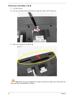
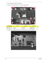
Remove the one screw (C) securing the locker bracket and remove the locker bracket from the optical
disk drive module.
Removing the Back Cover
1.
See “Removing the Battery Pack” on page 36.
2.
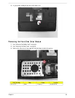
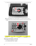
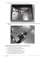
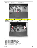
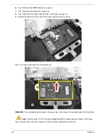
Release the three screws (A) and four captive screws securing the back cover.
Size (Quantity)
Color
Torque
Part No.
M2 x L3 (1)
Black
1.6 kgf-cm
86.00F80.723
Size (Quantity)
Color
Torque
Part No.
M2.5 x L6 (3)
Black
3.0 kgf-cm
86.00E12.536
Содержание Aspire 4350
Страница 6: ...VI ...
Страница 16: ...8 Chapter 1 5 USB 2 0 port Connect to USB 2 0 devices e g USB mouse USB camera Icon Item Description ...
Страница 26: ...18 Chapter 1 ...
Страница 40: ...32 Chapter 2 ...
Страница 76: ...68 Chapter 3 16 Detach the webcam cable from the webcam module 17 Disconnect the microphone cable ...
Страница 77: ...Chapter 3 69 18 Release the LCD cable from the tape 19 Remove the LCD panel with brackets from the back cover ...
Страница 84: ...76 Chapter 3 ...
Страница 106: ...98 Chapter 5 ...
Страница 108: ...100 Chapter 6 Exploded Diagram ...
Страница 109: ...Chapter 6 101 ...
Страница 121: ...Appendix A 113 Model Definition and Configuration Appendix A ...
Страница 146: ...138 Appendix B ...
Страница 148: ...140 Appendix C ...

