


Chapter 3
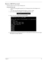
35
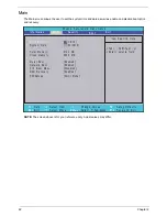
External Module Disassembly Process
External Modules Disassembly Flowchart
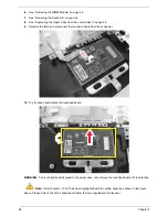
The flowchart below gives you a graphic representation on the entire disassembly sequence and instructs you
on the components that need to be removed during servicing. For example, if you want to remove the main
board, you must first remove the keyboard, then disassemble the inside assembly frame in that order.
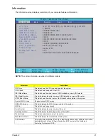
Item
Screw
Color
Part No.
A
M2.5 x L6
Black
86.00E12.536
B
M3 x L4
Silver
86.9A524.4R0
C
M2 x L3
Black
86.00F80.723
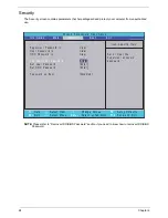
EXTERNAL MODULE DISASSEMBLY
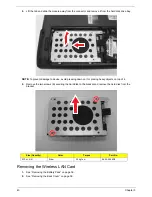
WLAN
BOARD
TURN OFF POWER
AND PERIPHERALS
UNPLUG POWER
CABLES
Cx1
BACK
COVER
DIMM
MODULES
REMOVE BATTERY
PACK
SD DUMMY CARD
Cx1
ODD
MODULE
OPTICAL DISK
DRIVE
OPTICAL
LOCKER
BRACKET
Bx2
HDD
MODULE
HARD DISK
BRACKET
HARD DISK
DRIVE
Cx1
Ax1
Ax3
Содержание Aspire 4350
Страница 6: ...VI ...
Страница 16: ...8 Chapter 1 5 USB 2 0 port Connect to USB 2 0 devices e g USB mouse USB camera Icon Item Description ...
Страница 26: ...18 Chapter 1 ...
Страница 40: ...32 Chapter 2 ...
Страница 76: ...68 Chapter 3 16 Detach the webcam cable from the webcam module 17 Disconnect the microphone cable ...
Страница 77: ...Chapter 3 69 18 Release the LCD cable from the tape 19 Remove the LCD panel with brackets from the back cover ...
Страница 84: ...76 Chapter 3 ...
Страница 106: ...98 Chapter 5 ...
Страница 108: ...100 Chapter 6 Exploded Diagram ...
Страница 109: ...Chapter 6 101 ...
Страница 121: ...Appendix A 113 Model Definition and Configuration Appendix A ...
Страница 146: ...138 Appendix B ...
Страница 148: ...140 Appendix C ...