


54
Chapter 3
3.
See “Removing the Back Cover” on page 38.
4.
See “Removing the Hard Disk Drive Module” on page 39.
5.
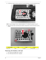
See “Removing the Wireless LAN Card” on page 40.
6.
See “Removing the DIMM Module” on page 42.
7.
See “Removing the Keyboard” on page 44.
8.
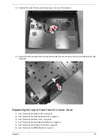
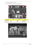
See “Separating the Upper Case from the Lower Case” on page 45.
9.
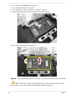
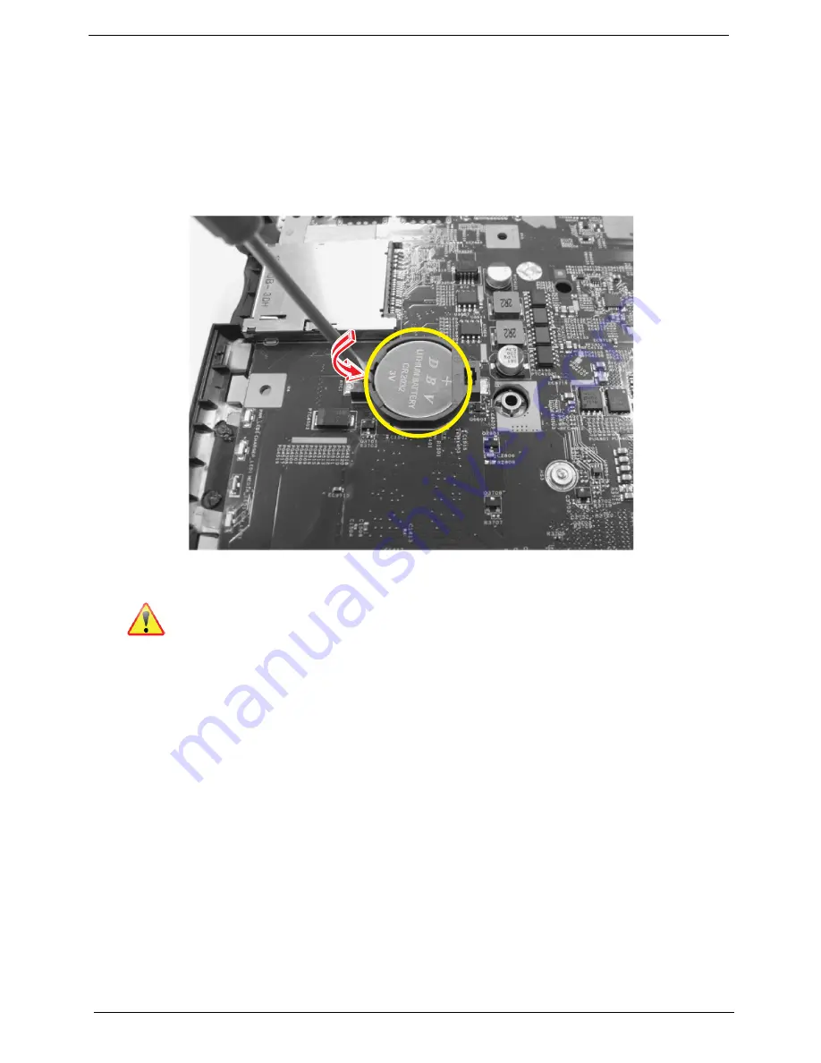
Use a flat screw driver to remove the RTC battery.
10.
Note:
RTC battery has been highlighted with the yellow circle as shown in the figure above. Please
detach the RTC battery and follow local regulations for disposal.
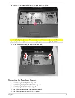
Removing the USB Board
1.
See “Removing the Battery Pack” on page 36.
2.
See “Removing the Optical Drive Module” on page 37.
3.
See “Removing the Back Cover” on page 38.
4.
See “Removing the Hard Disk Drive Module” on page 39.
5.
See “Removing the Wireless LAN Card” on page 40.
6.
See “Removing the DIMM Module” on page 42.
7.
See “Removing the Keyboard” on page 44.
8.
See “Separating the Upper Case from the Lower Case” on page 45.
Содержание Aspire 4350
Страница 6: ...VI ...
Страница 16: ...8 Chapter 1 5 USB 2 0 port Connect to USB 2 0 devices e g USB mouse USB camera Icon Item Description ...
Страница 26: ...18 Chapter 1 ...
Страница 40: ...32 Chapter 2 ...
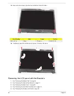
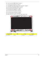
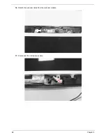
Страница 76: ...68 Chapter 3 16 Detach the webcam cable from the webcam module 17 Disconnect the microphone cable ...
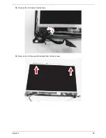
Страница 77: ...Chapter 3 69 18 Release the LCD cable from the tape 19 Remove the LCD panel with brackets from the back cover ...
Страница 84: ...76 Chapter 3 ...
Страница 106: ...98 Chapter 5 ...
Страница 108: ...100 Chapter 6 Exploded Diagram ...
Страница 109: ...Chapter 6 101 ...
Страница 121: ...Appendix A 113 Model Definition and Configuration Appendix A ...
Страница 146: ...138 Appendix B ...
Страница 148: ...140 Appendix C ...