


System Introduction
1-
33
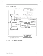
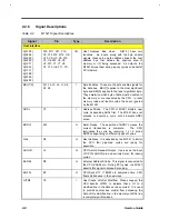
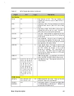
A necessary condition for the notebook to enter hibernation mode is that the reserved space for saving
system information on the hard disk must be larger than the combined system and video memory size.
Under such conditions, the standby/hibernation hotkey acts as the hibernation hotkey. See the user’s
manual for information on the Sleep Manager utility.
In this situation, there are four ways to enter hibernation mode:
•
Press the standby/hibernation hotkey Fn-F7 ( )
•
Set a value for the System Standby/Hibernation Timer in Setup. If the waiting time specified by this
time elapses without any system activity, the system goes into hibernation mode
•
Enable the Suspend upon Battery-low parameter in Setup. If a battery-low condition takes place, the
notebook enters hibernation mode in about five minutes.
•
Invoked by the operating system power saving modes
When the notebook enters hibernation mode, the whole system does not consume any power. This is why
hibernation mode is also called zero-volt suspend.
To exit hibernation mode, press the power switch (
).
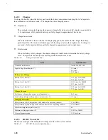
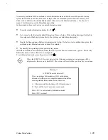
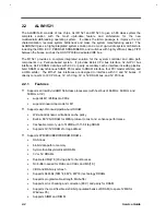
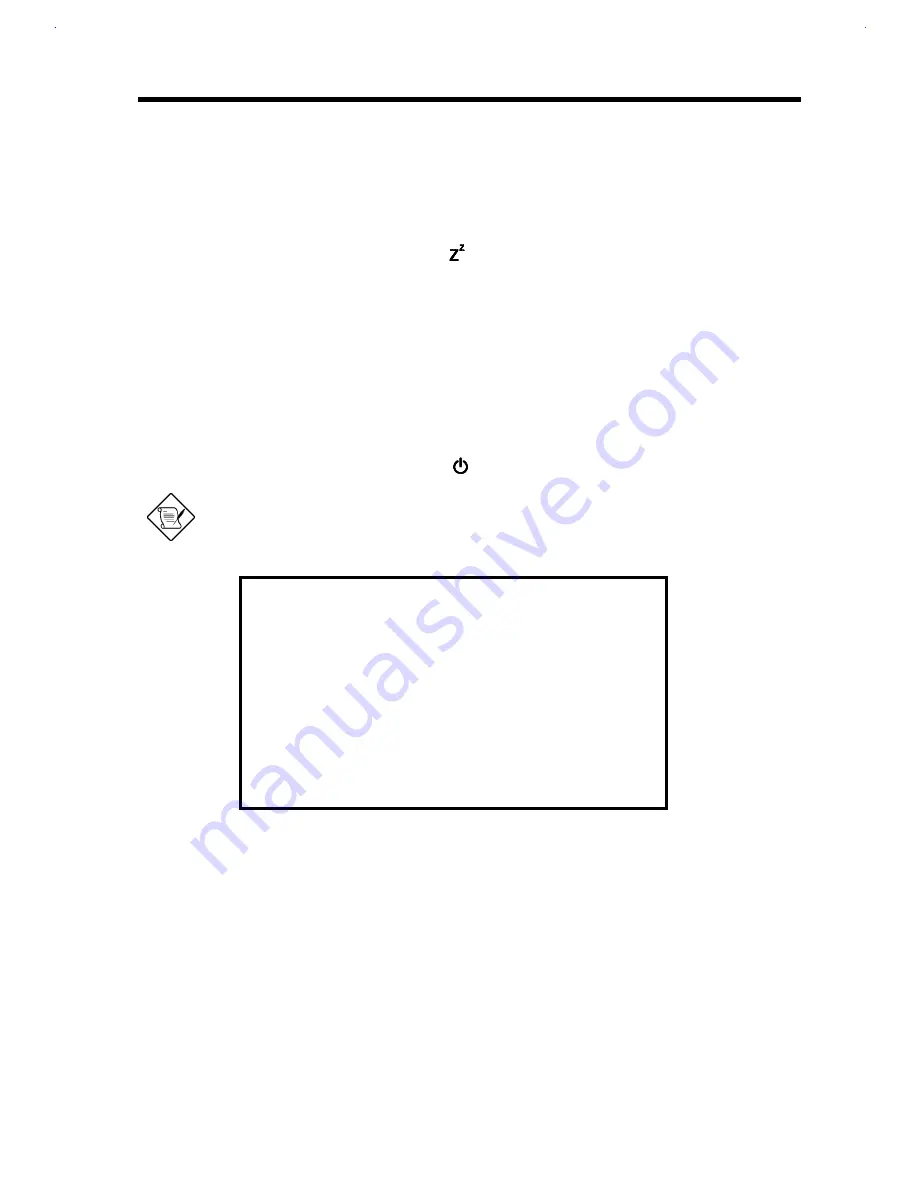
When the PCMCIA I/O card is detected, the following warning pop-up message will be
displayed on the screen by the BIOS. The system will wait for the specified key to continue.
Warning!!
A PCMCIA card is detected!!
If you are using a fax/modem or LAN cards, please
disconnect with server or complete transmission before
entering standby/hibernation mode, otherwise :
1)
File server will be shut down if LAN card is used.
2)
Data will be lost if a modem card is used.
Press <F1> to enter standby/hibernation mode.
Press <F2> to cancel.
Содержание AcerNote Light 370P
Страница 1: ...TI Extensa 61X Series AcerNote 370P Notebook Service Guide PART NO 2238309 0809 DOC NO PRINTED IN USA ...
Страница 6: ...vi ...
Страница 26: ...1 8 Service Guide Figure 1 5 Main Board Layout Bottom Side ...
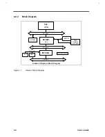
Страница 49: ...System Introduction 1 31 1 5 1 3 Power Management Figure 1 14 Power Management Block Diagram ...
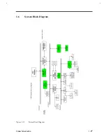
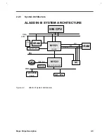
Страница 55: ...System Introduction 1 37 1 6 System Block Diagram Figure 1 15 System Block Diagram ...
Страница 64: ...Major Chips Description 2 7 2 2 5 Pin Diagram Figure 2 4 M1521 Pin Diagram ...
Страница 99: ...2 42 Service Guide 2 5 3 Pin Diagram Figure 2 10 C T 65550 Pin Diagram ...
Страница 116: ...Major Chips Description 2 59 2 6 4 Block Diagram Figure 2 11 Functional Block Diagram 16 bit PC Card Interface ...
Страница 117: ...2 60 Service Guide Figure 2 12 Functional block diagram CardBus Card Interface ...
Страница 118: ...Major Chips Description 2 61 2 6 5 Pin Diagram Figure 2 13 PCI to PC Card 16 bit terminal assignments ...
Страница 119: ...2 62 Service Guide Figure 2 14 PCI to CardBus terminal assignments ...
Страница 135: ...2 78 Service Guide 2 7 3 Pin Diagram Figure 2 16 NS87336VJG Pin Diagram ...
Страница 145: ...2 88 Service Guide 2 8 2 Pin Diagram Figure 2 17 YMF715 Block Diagram ...
Страница 185: ...Disassembly and Unit Replacement 4 5 Figure 4 3 Disassembly Sequence Flowchart ...
Страница 209: ...B 2 Service Guide ...
Страница 210: ...Exploded View Diagram B 3 ...
Страница 217: ...A p p e n d i x D A p p e n d i x D Schematics This appendix shows the schematic diagrams of the notebook ...


