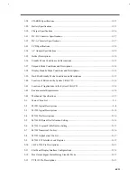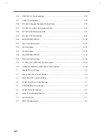
iii
About this Manual
Purpose
This service guide contains reference information for the Extensa 610 notebook computer. It gives the
system and peripheral specifications, shows how to identify and solve system problems and explains the
procedure for removing and replacing system components. It also gives information for ordering spare
parts.
Manual Structure
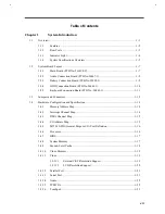
This service guide consists of four chapters and seven appendices as follows:
Chapter 1
System Introduction
This chapter gives the technical specifications for the notebook and its peripherals.
Chapter 2
Major Chip Descriptions
This chapter lists the major chips used in the notebook and includes pin descriptions and related
diagrams of these chips.
Chapter 3
BIOS Setup Information
This chapter includes the system BIOS information, focusing on the BIOS setup utility.
Chapter 4
Disassembly and Unit Replacement
This chapter tells how to disassemble the notebook and replace components.
Appendix A
Model Number Definition
This appendix lists the model number definition of this notebook model series.
Appendix B
Exploded View Diagram
This appendix shows the exploded view diagram of the notebook.
Appendix C
Spare Parts List
This appendix contains spare parts information.
Appendix D
Schematics
This appendix contains the schematic diagrams of the notebook.
Содержание AcerNote Light 370P
Страница 1: ...TI Extensa 61X Series AcerNote 370P Notebook Service Guide PART NO 2238309 0809 DOC NO PRINTED IN USA ...
Страница 6: ...vi ...
Страница 26: ...1 8 Service Guide Figure 1 5 Main Board Layout Bottom Side ...
Страница 49: ...System Introduction 1 31 1 5 1 3 Power Management Figure 1 14 Power Management Block Diagram ...
Страница 55: ...System Introduction 1 37 1 6 System Block Diagram Figure 1 15 System Block Diagram ...
Страница 64: ...Major Chips Description 2 7 2 2 5 Pin Diagram Figure 2 4 M1521 Pin Diagram ...
Страница 99: ...2 42 Service Guide 2 5 3 Pin Diagram Figure 2 10 C T 65550 Pin Diagram ...
Страница 116: ...Major Chips Description 2 59 2 6 4 Block Diagram Figure 2 11 Functional Block Diagram 16 bit PC Card Interface ...
Страница 117: ...2 60 Service Guide Figure 2 12 Functional block diagram CardBus Card Interface ...
Страница 118: ...Major Chips Description 2 61 2 6 5 Pin Diagram Figure 2 13 PCI to PC Card 16 bit terminal assignments ...
Страница 119: ...2 62 Service Guide Figure 2 14 PCI to CardBus terminal assignments ...
Страница 135: ...2 78 Service Guide 2 7 3 Pin Diagram Figure 2 16 NS87336VJG Pin Diagram ...
Страница 145: ...2 88 Service Guide 2 8 2 Pin Diagram Figure 2 17 YMF715 Block Diagram ...
Страница 185: ...Disassembly and Unit Replacement 4 5 Figure 4 3 Disassembly Sequence Flowchart ...
Страница 209: ...B 2 Service Guide ...
Страница 210: ...Exploded View Diagram B 3 ...
Страница 217: ...A p p e n d i x D A p p e n d i x D Schematics This appendix shows the schematic diagrams of the notebook ...


