System Introduction
1-
15
1
1
1
2
2
2
2
1
2
3
4
5
6
7
0083
0081
0082
Cascade
008B
0089
008A
Audio
Diskette
Audio (option)/ECP(option)
Cascade
-
Spare
-
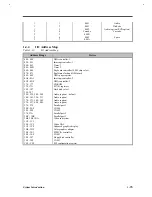
1.4.4
I/O Address Map
Table 1-10
I/O Address Map
Address Range
Device
000 - 00F
020 - 021
040 - 043
048 - 04B
060 - 064
070 - 071
080 - 08F
0A0 - 0A1
0C0 - 0DF
170 - 177
178, 17A
1F0 - 1F7
3F6, 3F7
220 - 22F, 240 - 24F
300 - 301, 330 - 331
370 - 371, 388 - 38F
530 - 537, E80 - E89
278 - 27F
2E8 - 2EF
2F8 - 2FF
378, 37A
3BC - 3BE
3B4, 3B5, 3BA
3C0 - 3C5
3C6 - 3C9
3C0 - 3CF
3D0 - 3DF
3E0 - 3E1
3E8 - 3EF
3F0 - 3F7
3F8 - 3FF
CF8 - CFF
DMA controller-1
Interrupt controller-1
Timer 1
Timer 2
Keyboard controller 38802 chip select
Real-time clock and NMI mask
DMA page register
Interrupt controller-2
DMA controller-2
CD-ROM
M7101 registers
Hard disk select
Audio (option) - default
Audio (option)
Audio (option)
Audio (option)
Parallel port 3
COM 4
COM 2
Parallel port 2
Parallel port 1
Video subsystem
Video DAC
Enhanced graphics display
Color graphics adapter
PCMCIA controller
COM3
Floppy disk controller
COM 1
PCI configuration register
Содержание AcerNote Light 370P
Страница 1: ...TI Extensa 61X Series AcerNote 370P Notebook Service Guide PART NO 2238309 0809 DOC NO PRINTED IN USA ...
Страница 6: ...vi ...
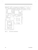
Страница 26: ...1 8 Service Guide Figure 1 5 Main Board Layout Bottom Side ...
Страница 49: ...System Introduction 1 31 1 5 1 3 Power Management Figure 1 14 Power Management Block Diagram ...
Страница 55: ...System Introduction 1 37 1 6 System Block Diagram Figure 1 15 System Block Diagram ...
Страница 64: ...Major Chips Description 2 7 2 2 5 Pin Diagram Figure 2 4 M1521 Pin Diagram ...
Страница 99: ...2 42 Service Guide 2 5 3 Pin Diagram Figure 2 10 C T 65550 Pin Diagram ...
Страница 116: ...Major Chips Description 2 59 2 6 4 Block Diagram Figure 2 11 Functional Block Diagram 16 bit PC Card Interface ...
Страница 117: ...2 60 Service Guide Figure 2 12 Functional block diagram CardBus Card Interface ...
Страница 118: ...Major Chips Description 2 61 2 6 5 Pin Diagram Figure 2 13 PCI to PC Card 16 bit terminal assignments ...
Страница 119: ...2 62 Service Guide Figure 2 14 PCI to CardBus terminal assignments ...
Страница 135: ...2 78 Service Guide 2 7 3 Pin Diagram Figure 2 16 NS87336VJG Pin Diagram ...
Страница 145: ...2 88 Service Guide 2 8 2 Pin Diagram Figure 2 17 YMF715 Block Diagram ...
Страница 185: ...Disassembly and Unit Replacement 4 5 Figure 4 3 Disassembly Sequence Flowchart ...
Страница 209: ...B 2 Service Guide ...
Страница 210: ...Exploded View Diagram B 3 ...
Страница 217: ...A p p e n d i x D A p p e n d i x D Schematics This appendix shows the schematic diagrams of the notebook ...

