Major Chips Description
2-73
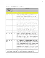
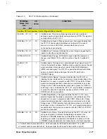
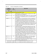
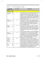
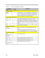
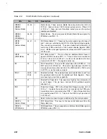
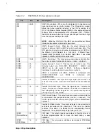
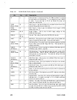
Table 2-13
PCI1131 Pin Descriptions (Continued)
TERMINAL
NAME NO
I /O TYPE
FUNCTION
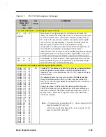
Interrupt Terminals
IRQ3/INTA 154
IRQ4/INTB 155
O
Interrupt Request 3 and Interrupt Request 4. These terminals
may be connected to either PCI or ISA interrupts. These
terminals are software configurable as IRQ3 or T1VTA, and
as IRQ4 or T1~. When configured for IRQ3 and IRQ4, these
terminals should be connected to the ISA IRQ programmable
interrupt controller. When these pins are configured for INTA
and INTB, these terminals should be connected to available
interrupts on the PCI bus.
IRQ7/
PCDMAREQ 157
O
Interrupt Request 7. This terminal is software configurable
and is used by the PCI1131 to request PC/PCI DMA transfers
from chip sets that support the PC/PCI DMA scheme. When
this pin is configured for PC/PCI DMA request (IRQ7) it
should be connected to the appropriate request (REQ#) pin
on the Intel MPIIX controller.
IRQ9/
IRQSER 158
O
Interrupt Request 9. This terminal is software configurable
and indicates an interrupt request from one of the PC Cards.
When this pin is configured for IRQ9 it should be connected
to the IRQ programmable interrupt controller. IRQSER allows
all IRQ signals to be serialized onto one pin. This signal is
configured
in the Device Control Register of the TI Extension Registers.
IRQ11/
PCDMAGNT 160
O
Interrupt Request 11. This terminals software configurable
and is used by the PCI 1131 to accept a grant for PC/PCI
DMA transfers from chip sets that support the PC/PCI DMA
scheme. When this pin is configured for PC/PCI DMA grant
(IRQ11) it should be connected to the appropriate grant
(GNT#) pin on the Intel MPIIX controller.
IRQ10/
CLKRUM 159
IRQ12/
CLKRUM 161
I/O
Interrupt Request 10 and t2. This terminal is software
configurable and is used by the PCI1131 to support the PCI
Clock Run protocol. When configured as CLKRUN, by setting
bit 0 in the System Control Register at offset 80h (Section
7.27), this terminal is an open drain output. To select between
IRQ10 and IRQ12 as the output use bit 7 of Register 80h.
IRQ5 156
IRQ14
162
O
Interrupt Requests 5 and 14. These signals are ISA interrupts.
These terminals indicate an interrupt request from one of the
PC Cards. The Interrupt mode is selected in the Device
Control Register of the TI Extension Registers.
Содержание AcerNote Light 370P
Страница 1: ...TI Extensa 61X Series AcerNote 370P Notebook Service Guide PART NO 2238309 0809 DOC NO PRINTED IN USA ...
Страница 6: ...vi ...
Страница 26: ...1 8 Service Guide Figure 1 5 Main Board Layout Bottom Side ...
Страница 49: ...System Introduction 1 31 1 5 1 3 Power Management Figure 1 14 Power Management Block Diagram ...
Страница 55: ...System Introduction 1 37 1 6 System Block Diagram Figure 1 15 System Block Diagram ...
Страница 64: ...Major Chips Description 2 7 2 2 5 Pin Diagram Figure 2 4 M1521 Pin Diagram ...
Страница 99: ...2 42 Service Guide 2 5 3 Pin Diagram Figure 2 10 C T 65550 Pin Diagram ...
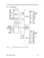
Страница 116: ...Major Chips Description 2 59 2 6 4 Block Diagram Figure 2 11 Functional Block Diagram 16 bit PC Card Interface ...
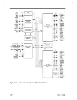
Страница 117: ...2 60 Service Guide Figure 2 12 Functional block diagram CardBus Card Interface ...
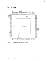
Страница 118: ...Major Chips Description 2 61 2 6 5 Pin Diagram Figure 2 13 PCI to PC Card 16 bit terminal assignments ...
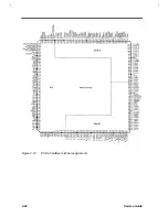
Страница 119: ...2 62 Service Guide Figure 2 14 PCI to CardBus terminal assignments ...
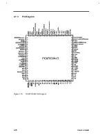
Страница 135: ...2 78 Service Guide 2 7 3 Pin Diagram Figure 2 16 NS87336VJG Pin Diagram ...
Страница 145: ...2 88 Service Guide 2 8 2 Pin Diagram Figure 2 17 YMF715 Block Diagram ...
Страница 185: ...Disassembly and Unit Replacement 4 5 Figure 4 3 Disassembly Sequence Flowchart ...
Страница 209: ...B 2 Service Guide ...
Страница 210: ...Exploded View Diagram B 3 ...
Страница 217: ...A p p e n d i x D A p p e n d i x D Schematics This appendix shows the schematic diagrams of the notebook ...

