2-5
System Utilities
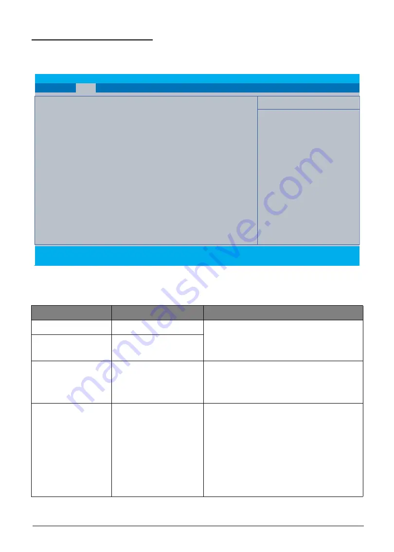
Main Tab (Windows 10)
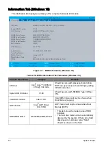
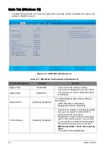
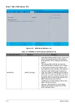
The Main tab allows the user to set the system time and date, enable or disable boot option, and
enable or disable recovery.
Figure 2-2. BIOS Main (Windows 10)
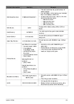
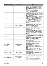
Table 2-11. BIOS Main Tab Parameters (Windows 10)
Product Information
Example
Remark
System Time
HH:MM:SS
• The format is the number of string.
• The hours are displayed in 24-hour format.
• The values set in the two fields take effect
immediately.
System Date
MM/DD/YY
Network Boot
[Enabled] / [Disabled]
The default Network Boot value in different
Boot Modes:
• [UEFI] Boot Mode : [Disabled]
• [Legacy] Boot Mode : [Enabled]
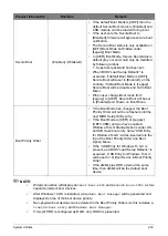
F12 Boot Menu
[Enabled] / [Disabled]
• This function enables or disables the ability
that user can press F12 while POST to
quickly select the boot device.
• Modification to the boot device order apply
only for the current session. The next time
your computer is rebooted it will use again
the boot device sequence as set in the
BIOS Setup Utility
>
Boot
>
Boot priority
order:
.
• The default value is [Disabled].
InsydeH20 Setup Utility
Rev. 5.0
F1
Help
Select Item
F5/F6
Change Values
F9
Setup Defaults
Esc
Exit
Select Menu
Enter
Select
►
Sub-Menu
F10
Save and Exit
System Time :
[
19
:10:49]
System Date :
[01/01/2017]
Network Boot:
[Disabled]
F12 Boot Menu:
[Disabled]
Wake on LAN:
[Disabled]
Touchpad: [Advanced]
Lid Open Resume:
[Enabled]
Wake on USB while lid closed [Disabled]
D2D Recovery:
[Enabled]
GPT Partition Recovery:
[None]
Clear GPT Partition
[None]
GPT Partition Record:
No Record
Information
Main
Advanced Security Boot Exit
Item Specific Help
Hour valid range is from 0 to 23.
Minute Valid range is from 0
to 59. Second Valid range is from 0 to
59. REDUCE/INCREASE : F5/F6.
Содержание A315-53G
Страница 1: ...A315 53 A315 53G S E R V I C E G U I D E ...
Страница 12: ...1 5 Hardware Specifications and Configurations Warranty One year International Travelers Warranty ITW ...
Страница 22: ...1 15 Hardware Specifications and Configurations System Block Diagram Figure 1 7 System Block Diagram UMA ...
Страница 23: ...Hardware Specifications and Configurations 1 16 Figure 1 8 System Block Diagram Discrete ...
Страница 149: ...Service and Maintenance 5 9 Table 5 9 RAM Door Screw Screw Name Screw Type Torque Quantity M 2 5 x 6 0 2 55 3 0kgf cm 1 ...
Страница 224: ...5 84 Service and Maintenance Figure 5 129 Disconnecting the Cables UMA C A F D B E G H I ...
Страница 230: ...5 90 Service and Maintenance Figure 5 139 Connecting the Cables UMA C A F D B E G H I ...
Страница 301: ...CHAPTER 8 Online Support Information Online Support Information 8 2 Introduction 8 2 ...
Страница 303: ......

