Service and Maintenance
5-89
3.
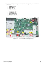
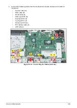
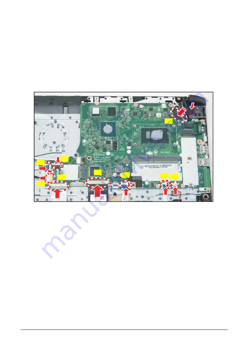
Connect the following cables from the mainboard connectors and secure the latch (if
necessary):
•
Speaker cable (A)
•
HDD cable (B)
•
DC-IN cable (C)
•
USB board FFC (D)
•
Keyboard FPC (E)
•
Touchpad FFC (F)
•
Hall sensor FFC (G)
•
RTC battery cable (H)
•
eDP cable (I)
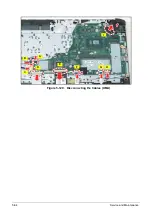
Figure 5-138. Connecting the Cables (Discrete)
C
A
F
D
B
E
G
H
I
Содержание A315-53G
Страница 1: ...A315 53 A315 53G S E R V I C E G U I D E ...
Страница 12: ...1 5 Hardware Specifications and Configurations Warranty One year International Travelers Warranty ITW ...
Страница 22: ...1 15 Hardware Specifications and Configurations System Block Diagram Figure 1 7 System Block Diagram UMA ...
Страница 23: ...Hardware Specifications and Configurations 1 16 Figure 1 8 System Block Diagram Discrete ...
Страница 149: ...Service and Maintenance 5 9 Table 5 9 RAM Door Screw Screw Name Screw Type Torque Quantity M 2 5 x 6 0 2 55 3 0kgf cm 1 ...
Страница 224: ...5 84 Service and Maintenance Figure 5 129 Disconnecting the Cables UMA C A F D B E G H I ...
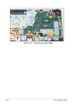
Страница 230: ...5 90 Service and Maintenance Figure 5 139 Connecting the Cables UMA C A F D B E G H I ...
Страница 301: ...CHAPTER 8 Online Support Information Online Support Information 8 2 Introduction 8 2 ...
Страница 303: ......

