5-4
Service and Maintenance
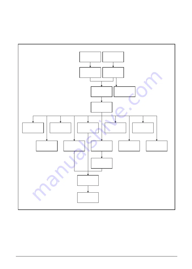
Maintenance Flowchart
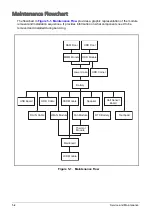
The flowchart in
provides a graphic representation of the module
removal and installation sequences. It provides information on what components need to be
removed and installed during servicing.
Figure 5-1. Maintenance Flow
SSD Module
Thermal
Module
DC-IN Cable
HDD Cable
Fan Module
Speaker
WLAN Module
USB Board
Hall Sensor
Board
RTC Battery
Touchpad
DIMM Module
HDD Door
HDD Module
HDD Carrier
Lower Case
Battery
RAM Door
Mainboard
LCD Module
Содержание A315-53G
Страница 1: ...A315 53 A315 53G S E R V I C E G U I D E ...
Страница 12: ...1 5 Hardware Specifications and Configurations Warranty One year International Travelers Warranty ITW ...
Страница 22: ...1 15 Hardware Specifications and Configurations System Block Diagram Figure 1 7 System Block Diagram UMA ...
Страница 23: ...Hardware Specifications and Configurations 1 16 Figure 1 8 System Block Diagram Discrete ...
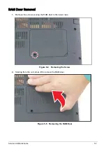
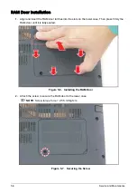
Страница 149: ...Service and Maintenance 5 9 Table 5 9 RAM Door Screw Screw Name Screw Type Torque Quantity M 2 5 x 6 0 2 55 3 0kgf cm 1 ...
Страница 224: ...5 84 Service and Maintenance Figure 5 129 Disconnecting the Cables UMA C A F D B E G H I ...
Страница 230: ...5 90 Service and Maintenance Figure 5 139 Connecting the Cables UMA C A F D B E G H I ...
Страница 301: ...CHAPTER 8 Online Support Information Online Support Information 8 2 Introduction 8 2 ...
Страница 303: ......

