5-40
Service and Maintenance
3.
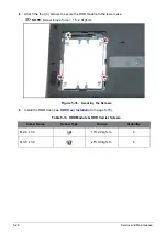
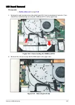
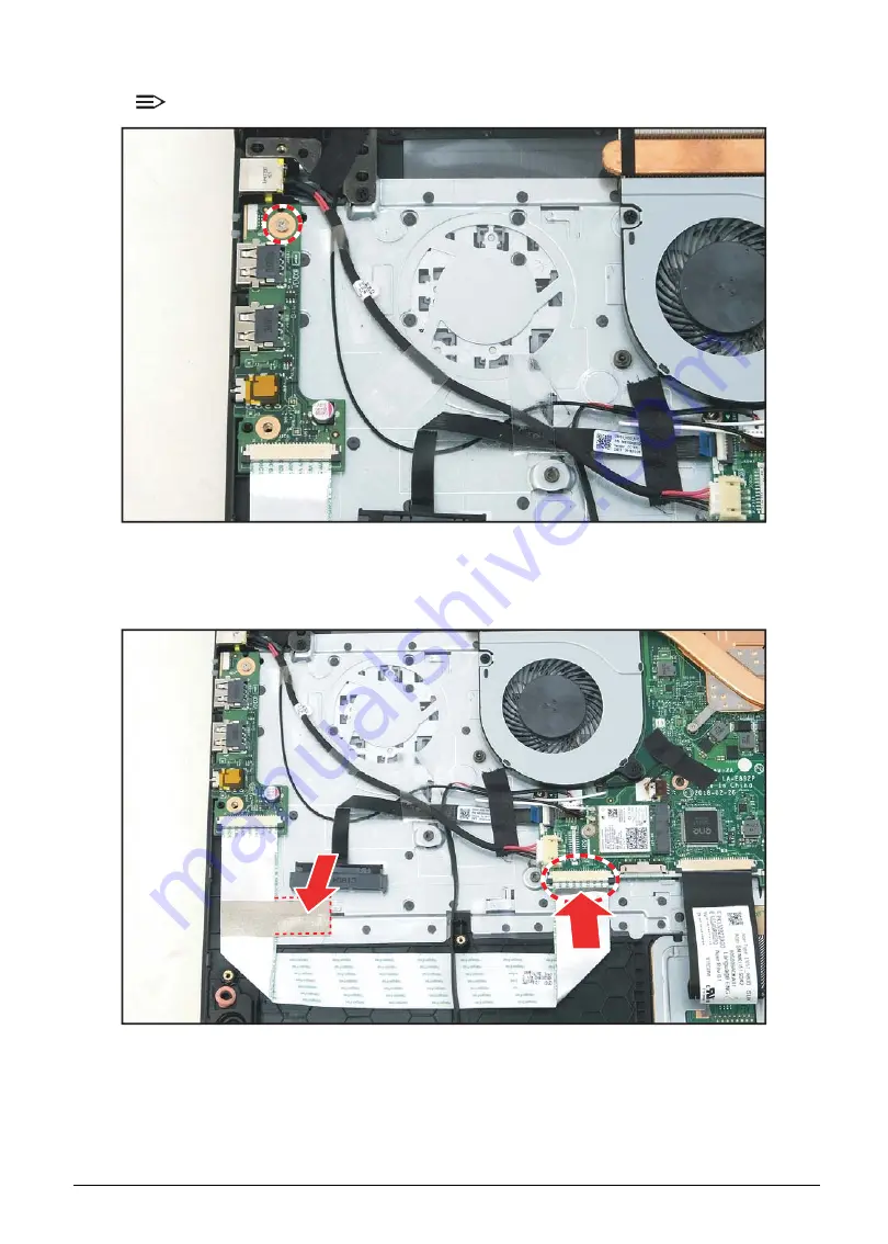
Attach the screw to secure the USB board to the upper case.
NOTE:
Screw torque force = 1.8~2.2kgf.cm
Figure 5-56. Securing the Screw
4.
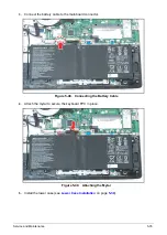
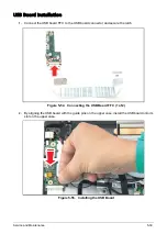
Connect the USB board FFC to the mainboard connector and secure the latch. Then attach the
conductive tape to secure the USB board FFC in place.
Figure 5-57. Connecting the USB Board FFC (2 of 2)
5.
Install the battery (see
).
Содержание A315-53G
Страница 1: ...A315 53 A315 53G S E R V I C E G U I D E ...
Страница 12: ...1 5 Hardware Specifications and Configurations Warranty One year International Travelers Warranty ITW ...
Страница 22: ...1 15 Hardware Specifications and Configurations System Block Diagram Figure 1 7 System Block Diagram UMA ...
Страница 23: ...Hardware Specifications and Configurations 1 16 Figure 1 8 System Block Diagram Discrete ...
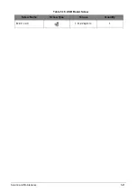
Страница 149: ...Service and Maintenance 5 9 Table 5 9 RAM Door Screw Screw Name Screw Type Torque Quantity M 2 5 x 6 0 2 55 3 0kgf cm 1 ...
Страница 224: ...5 84 Service and Maintenance Figure 5 129 Disconnecting the Cables UMA C A F D B E G H I ...
Страница 230: ...5 90 Service and Maintenance Figure 5 139 Connecting the Cables UMA C A F D B E G H I ...
Страница 301: ...CHAPTER 8 Online Support Information Online Support Information 8 2 Introduction 8 2 ...
Страница 303: ......

