ENGLISH
ESPAÑOL
730 PRO
9
COD. 104064 Rev.0
9
10
11
12
13
INSTALLATION
POSITIONING THE MACHINE
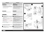
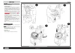
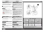
» Release the 4 nuts fixing the machine to the pallet (fig.9).
» Wrap the lifting sling A (mod. DR250 of 3 ft.) and sling B (mod.FA650
of 10 ft.) as in fig.10 taking care not to crush the cylinder supply pipes.
» Lift the machine and place it in the established area respecting the
distances indicated by the fig.8 (pag.14).
»
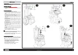
Mount the tire-holder pipe as in fig.11.
PNEUMATIC CONNECTION
»
Connect the machine to the pneumatic system as in fig.12.
ELECTRICAL CONNECTION
»
Connect the machine to the mains.
ALL WORK ON THE ELECTRICAL SYSTEM, INCLUDING MINOR
OPERATIONS, MUST BE CARRIED OUT BY PROFESSIONALLY
QUALIFIED PERSONNEL !
»
Check that the mains supply voltage is the same as that shown on the
registration plate.
»
Connect the supply cable to a plug that conforms with European norms
or to the norms of the country in which the machine is used. The plug
must have an ground terminal.
»
Check that the ground connection is effective.
»
The machine must be connected to the mains through a multipole
isolating switch which conforms with European norms and with con-
tact openings of at least 0.04”.
N.B.
: THE ELECTRICAL CIRCUIT DIAGRAMS ARE LOCATED IN THE
ELECTRICAL PANEL OF THE MACHINE
THE MANUFACTURER DECLINES ALL RESPONSIBILITY FOR FAIL-
URE TO OBSERVE THE ABOVE INSTRUCTIONS.
It is very important for the correct operation of the machine
that downward pressure on the inverter pedal produces a
clockwise rotation of the chuck
(fig.13).
INSTALACIÓN
COLOCACIÓN DE LA MÁQUINA
»
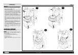
Destornillar las 4 tuercas que fijan la máquina al palet (fig.9).
»
Pasar la faja A de levantamiento (mod. DR250 de 3 ft.) y la faja B
(mod.FA650 de 10 ft.) como se ve en la fig.10 prestando atención a no
aplastar los tubos de alimentación de los cilindros.
»
Levantar la máquina y colocar en la zona preestablecida respetando
las distancias indicadas en la fig.8 (pag.14).
»
Montar el tubo portagomas como se ve en la fig.11.
CONEXIÓN NEUMÁTICA
»
Conectar la máquina a la red neumática como se ve en la fig.12.
CONEXIÓN ELÉCTRICA
»
Conectar la máquina a la red eléctrica
¡TODA INTERVENCIÓN EN LA INSTALACIÓN ELÉCTRICA, POR
INSIGNIFICANTE QUE SEA, DEBE SER EFECTUADA POR PER-
SONAL PROFESIONALMENTE CALIFICADO !
»
Controlar que la tensión de línea sea conforme a la indicada en la placa
de la máquina.
»
Conectar el cable de la alimentación a un enchufe conforme a las
normas Europeas o del país de destino de la máquina. El enchufe debe
estar obligatoriamente dotado de contacto de tierra.
»
Controlar la eficacia de la toma de tierra.
»
La máquina debe estar conectada a la red mediante un seccionador
omnipolar conforme a las normas Europeas, con un mínimo de 0.04”
de apertura de los contactos.
NOTA:
LOS PLANOS DE LOS ESQUEMAS ELÉCTRICOS ESTÁN
SITUADOS EN EL CUADRO ELÉCTRICO DE LA MÁQUINA
EL FABRICANTE NO ASUME RESPONSABILIDAD ALGUNA SI NO SE
OBSERVAN DEBIDAMENTE ESTAS PRESCRIPCIONES.
Es muy importante, para el buen funcionamiento de la
máquina, que al pisar el pedal de inversión el autocentrante
gire en el sentido de las agujas del reloj
(fig.13).
switch
American standards
standards
there is proper grounding.
supply
American standards
switch
Содержание 730 PRO
Страница 18: ......
Страница 20: ...N 104006 Rev 0 730 PRO...
Страница 22: ...N 104007 Rev 0 730 PRO...
Страница 24: ...N 104008 Rev 0 730 PRO...
Страница 26: ...N 104009 Rev 0 730 PRO...
Страница 28: ...N 104010 Rev 0 730 PRO...
Страница 30: ...N 104011 Rev 0 730 PRO...
Страница 32: ...N 104012 Rev 0 730 PRO...
Страница 34: ...N 104013 Rev 0 730 PRO...
Страница 36: ...N 104014 Rev 0 730 PRO...
Страница 38: ...N 104015 Rev 0 730 PRO...
Страница 40: ...N 104016 Rev 0 730 PRO...
Страница 42: ...N 104036 Rev 0 OPTIONAL...
Страница 43: ...1 104055 3 4 5 REVERSED HOLES FLANGE GROUP...


