


ENGLISH
ESPAÑOL
5
COD. 104064 Rev.0
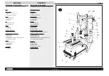
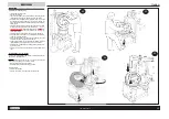
COMPONENT PARTS
HYDRAULIC BEAD-BREAKER GROUP
The tire changer is equipped with a hydraulic roller bead-breaker for safe bead-breaking of tires mounted on alloy or painted rims, consisting of:
»
Nylon rollers
, (fig.1-13) mounted on fixed arms operating in perfect symmetry to help the operator when preparing bead-breaking.
The symmetrical action of the Teflon rollers combined with the movement of the chuck allows optimum efficiency when bead-breaking without
causing any damage to the rim or tire.
»
The upper roller arm
(fig.1-14) can be disengaged by extracting the fixing pin to facilitate mounting operations.
»
The lower roller arm
(fig.1-15) as well as functioning as a bead-breaker, is particularly useful for preventing tires from beading back in during
demounting and for helping the extraction process.
»
The third operating arm
(fig.1-16) is particularly useful for preventing particularly difficult tires from beading back in.
»
The
control panel
(fig.1-17) activates all hydraulic movements (see controls section)
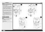
MOVABLE CHUCK
The backwards and forwards movement of the chuck (ACCU-TURN patent) is fundamental for allowing bead-breaking regardless of rim format.
The chuck is powered pneumatically by two cylinders and consists of:
»
The rim locking device
(fig.1-4/6), with locking flange (to which the cones and fixing wing nut are fitted) and specifically designed drive pin for
operating with special rims and tires.
»
The
universal plate
(fig.1-5), for rotating the rim in both directions without releasing it.
The casing dimensions allow work on wheels of up to 49”.
LIFT
The tire lifting device provides easy and precise positioning of tires for mounting and demounting.
The lift consists of:
»
The
mobile section
(fig.1-8), controlled with a pedal, for lifting tires off the floor and lowering back down when finished.
»
The
fixed section
(fig.1-7), with sliding rollers, on which the tire is positioned for mounting and demounting operations.
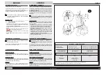
HELPER
The tire changer has a helper device, operating with hydraulic pressure for safe bead-breaking of all tires, even difficult-to-mount types. If consists of:
»
An
articulated arm
(fig.1-18), for positioning the helper.
»
A
helper roller
(fig.1-19/20), driven by a hydraulic cylinder, for applying pressure on the tire to assist beading.
COLUMN GROUP
The
column group
, supports the necessary components for demounting tires from rims (and for mounting):
»
The
articulated arm
(fig.1-1), for the positioning of the head.
»
The
head
(fig.1-2) for removing tires from rims with the help of the bead lever (see “Accessories provided” section) and for mounting.
»
The
storage space
(fig.1-3) consisting of shelf trays in the vertical column, for the equipment required for tire mounting and demounting operations.
» The sliding
roller
, inserted inside the head, avoids any friction between the head and rim during tire mounting and demounting.
»
The
tongue
: a special “protection tongue” designed for use with aluminium rims (see “Accessories on request” section).
TUBELESS TIRE INFLATION DEVICE (fig.1-12)
The IT (inflation tubeless) device incorporated in the machine has a large capacity air circuit and an instantaneous valve. The air exits from two holes
in each track. These are ideally positioned for any type of rim and can bead in any type of tire.
The machine also has a compressed air cylinder conforming to Directive 87/404 EEC. The cylinder capacity means that the operator always has 18
litres of compressed air available for the inflation of tubeless tires.
WARNING
!
THE INFLATION OF TIRES IS A POTENTIALLY DANGEROUS OPERATION!
SAFETY DEVICE
To protect the operator from potential danger resulting from the inflation of tires on the chuck plate, the machine is fitted with a
pressure limiting valve
set at 3.5 bar and a
maximum pressure valve
set at 4 bar.
PARTES Y COMPONENTES
GRUPO DESTALONADOR HIDRÁULICO
El desmontador de neumáticos cuenta con un destalonador hidráulico de rodillos para destalonar con toda seguridad los neumáticos montados en
llantas de aleación o barnizadas. Está formado por:
»
Los
Rodillos de nylon
(fig.1-13) montados sobre brazos fijos, actúan de manera simétrica para facilitar al operador la preparación de la fase de
destalonamiento.
»
La función simétrica de los rodillos de teflón, combinada con el movimiento del autocentrante, permite obtener la máxima operatividad durante el
destalonamiento sin dañar ni la llanta ni el neumático.
»
El
brazo del rodillo
superior (fig.1-14) puede soltarse para facilitar las operaciones de montaje; sólo hay que sacar el perno de sujeción..
»
El brazo del rodillo inferior
(fig.1-15) además su función genérica de destalonado, es especialmente útil para evitar que el talón vuelva a calzarse
en la llanta, facilitando así la extracción del neumático.
»
El tercer brazo operativo
(fig.1-16)
,
es particularmente útil para evitar que el talón vuelva a calzarse cuando se trabaja con neumáticos de montaje
especialmente difícil.
»
La
consola de control
(fig.1-17) acciona todos los movimientos hidráulicos (ver la sección de mandos)
AUTOCENTRANTE MÓVIL
El movimiento del autocentrante hacia adelante y hacia atrás (patentado por ACCU-TURN) es determinante a la hora de permitir el destalonado del
neumático, independientemente de la conformación de la llanta.
El autocentrante es accionado neumáticamente por 2 cilindros y está formado por:
» El
dispositivo de anclaje de la llanta
(fig.1-4/6), compuesto por la brida de bloqueo (a la que se aplican los conos y la palomilla de sujeción) y
la espiga de arrastre, estudiada y construida específicamente para su aplicación en llantas y neumáticos especiales.
»
El
plato universal
(fig.1-5), para girar la llanta en ambos sentidos sin desbloquearla.
El tamaño de la caja permite trabajar con ruedas de un diámetro máximo de 49”.
ELEVADOR
El dispositivo de elevación del neumático permite ajustar la posición del neumático para las operaciones de desmontaje y montaje de un modo simple
y preciso.
El elevador está formado por:
»
La
parte móvil
(fig.1-8), accionada por el pedal correspondiente, para levantar el neumático del suelo y colocarlo de nuevo una vez terminadas las
operaciones.
»
La
parte fija
(fig.1-7), con rodillos deslizantes, sobre la que se coloca el neumático para las operaciones de montaje y desmontaje.
ASISTENTE
El desmontador de neumáticos está equipado con un dispositivo de asistencia cuyo funcionamiento hidráulico a presión permite destalonar con
seguridad todos los neumáticos, y en particular aquellos de montaje más difícil. Está formado por:
»
El
brazo articulado
(fig.1-18), para ajustar la posición del asistente.
»
El
rodillo asistente
(fig.1-19/20), accionado por el cilindro hidráulico, para ejercer sobre el neumático una presión que ayuda a calzar el talón.
GRUPO BARRA
El
grupo
barra
, da cabida a los componentes necesarios para desmontar el neumático de la llanta (y para montarlo de nuevo) :
»
El
brazo articulado
(fig.1-1), para ajustar la posición de la torreta.
»
La
torreta
(fig.1-2) para quitar, con ayuda de la palanca alza-talones (ver sección “Accesorios de serie”) el neumática de la llanta (y para montarlo
de nuevo).
»
El
almacén
(fig.1-3) formado por varios compartimientos repartidos por la barra vertical que dan cabida a las herramientas necesarias en las
operaciones de montaje y desmontaje del neumático.
» El
rodillo de deslizamiento
, metido en el hueco de la torreta, para evitar el roce entre la llanta y la torreta durante las fases de desmontaje y montaje
del neumático.
» La
lengüeta
: para las llantas de aluminio se ha diseñado una “Lengüeta de protección” especial (ver sección “Accesorios bajo pedido”).
DISPOSITIVO PARA INFLADO DE TUBELESS (fig.1-12)
El
dispositivo it
(inflator tubeless) incorporado a la máquina está dotado de un circuito de aire de gran caudal y una válvula de apertura instantánea.
El aire sale a través de dos orificios por cada carril, perfectamente situados para llantas de todas las medidas, idóneos para lograr siempre el talonado
de cualquier neumático.
La máquina está además equipada con una
Bombona de aire comprimido
conforme a las disposiciones de la Directiva 87/404 CEE. La bombona
tiene una capacidad que permite al operador tener siempre a disposición 18 litros de aire comprimido para el inflado de los neumático tubeless.
¡ATENCIÓN!
EL INFLADO DEL NEUMÁTICO ES UNA OPERACIÓN POTENCIALMENTE PELIGROSA
DISPOSITIVO DE SEGURIDAD
Con objeto de proteger al operador de los peligros derivados de inflar el neumático en el plato autocentrante, la máquina está equipada con una
válvula
limitadora de la presión
de funcionamiento regulada a 3,5 bar y una
válvula de presión máxima
regulada a 4 bar.
cabinet
tank
tank
tank
tank
48 psi
55 psi
Содержание 730 PRO
Страница 18: ......
Страница 20: ...N 104006 Rev 0 730 PRO...
Страница 22: ...N 104007 Rev 0 730 PRO...
Страница 24: ...N 104008 Rev 0 730 PRO...
Страница 26: ...N 104009 Rev 0 730 PRO...
Страница 28: ...N 104010 Rev 0 730 PRO...
Страница 30: ...N 104011 Rev 0 730 PRO...
Страница 32: ...N 104012 Rev 0 730 PRO...
Страница 34: ...N 104013 Rev 0 730 PRO...
Страница 36: ...N 104014 Rev 0 730 PRO...
Страница 38: ...N 104015 Rev 0 730 PRO...
Страница 40: ...N 104016 Rev 0 730 PRO...
Страница 42: ...N 104036 Rev 0 OPTIONAL...
Страница 43: ...1 104055 3 4 5 REVERSED HOLES FLANGE GROUP...


