WSD/HDe
Digital Audio Option Installation
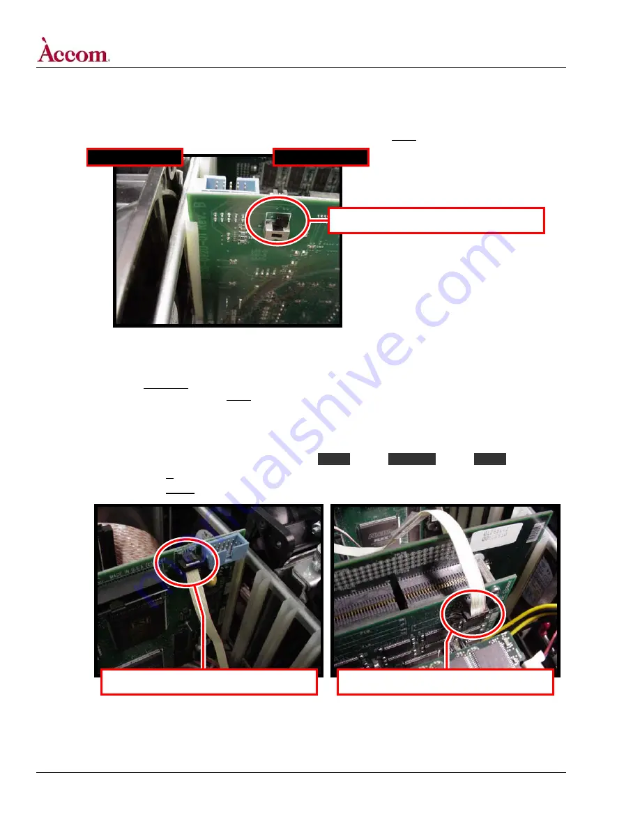
8. Set the termination switch S1 on the new Digital Audio PCI board.
A. Locate termination switch S1 on the new Digital Audio PCI card — it’s located (on the circuit side of the board) at the top end of
the card nearest the fan assemblies, as shown below. Push switch S1 towards the REAR of the WSD/HDe chassis.
FRONT of Chassis
REAR of Chassis
Location of switch S1 on the Digital Audio board.
9. Install the internal 10-pin ribbon cable (Part # 9000-0810-00) between the Digital Audio Board and the Video board.
A. If your WSD/HDe DOES NOT have the LTC-GPI Option installed: a yellow-colored 10-pin ribbon cable (with three connectors) is
supplied with this kit. If your WSD/HDe DOES have the LTC-GPI Option installed: inside the WSD/HDe chassis, the yellow-
colored 10-pin ribbon cable (with three connectors) will already be fitted between the Video board and the LTC-GPI board.
Install this cable as indicated in the next step.
B. Install the 10-Pin ribbon cable, with the three connectors (END / MIDDLE / END) on the cable connected as follows:
END
MIDDLE
END .
If LTC-GPI Option IS fitted in this WSD/HDe:
(Audio Board J8) (LTC-GPI Board J1) (Video Board J22)
If LTC-GPI Option IS NOT fitted in this WSD/HDe: (Audio Board J8) (NO CONNECTION)
(Video Board J22)
Digital Audio Board connector J8.
Video Board connector J22.
Continued on next page…
Page 6 of 15
©
2004 / Accom, Incorporated
Document Revised: 5-Nov-04 @ 8:09 AM


