Chapter 6: Connector Pin Assignments
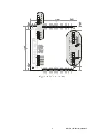
Two identical 50-pin right-angle headers are provided on the product, one for each 24-bit input group.
Port 0 is located on the same side as the address jumpers, while Port 1 is on the opposite side, near the
IRQ level jumpers. Connector pin assignments are listed below for Port 0. Port 1 follows the same pinout
but for bits 24-47.
PIN
NAME
PIN
NAME
1
GND
2
NC
3
Bit 0 A
4
Bit 0 B
5
Bit 1 A
6
Bit 1 B
7
Bit 2 A
8
Bit 2 B
9
Bit 3 A
10
Bit 3 B
11
Bit 4 A
12
Bit 4 B
13
Bit 5 A
14
Bit 5 B
15
Bit 6 A
16
Bit 6 B
17
Bit 7 A
18
Bit 7 B
19
Bit 8 A
20
Bit 8 B
21
Bit 9 A
22
Bit 9 B
23
Bit 10 A
24
Bit 10 B
25
Bit 11 A
26
Bit 11 B
27
Bit 12 A
28
Bit 12 B
29
Bit 13 A
30
Bit 13 B
31
Bit 14 A
32
Bit 14 B
33
Bit 15 A
34
Bit 15 B
35
Bit 16 A
36
Bit 16 B
37
Bit 17 A
38
Bit 17 B
39
Bit 18 A
40
Bit 18 B
41
Bit 19 A
42
Bit 19 B
43
Bit 20 A
44
Bit 20 B
45
Bit 21 A
46
Bit 21 B
47
Bit 22 A
48
Bit 22 B
49
Bit 23 A
50
Bit 23 B
Manual 104-IDI-48 SERIES
16

