Chapter 5: Programming
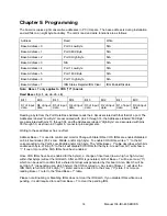
The board occupies eight consecutive addresses in PC I/O space. The base address is during installation
and will fall on an eight byte boundary. The card’s read and write functions are as follows:
Address
Read
Write
Base A 0
Port 0 Low Byte
N/A
Base A 1
Port 0 Mid Byte
N/A
Base A 2
Port 0 High Byte
N/A
Base A 3
N/A
N/A
Base A 4
Port 1 Low Byte
N/A
Base A 5
Port 1 Mid Byte
N/A
Base A 6
Port 1 High Byte
N/A
Base A 7
IRQ Status Register/IRQ Clear
IRQ Enable/Disable
Note: Base + 7 only applies to COS (“C”) boards
Read Base + 0 (+1, +2, +4, +5, +6)
Bit 7
Bit 6
Bit 5
Bit 4
Bit 3
Bit 2
Bit 1
Bit 0
D7 of input
data
D6 of input
data
D5 of input
data
D4 of input
data
D3 of input
data
D2 of input
data
D1 of input
data
D0 of input
data
Reading a byte from the Port Data Base Address reads the 8 bits associated with that third of a port. The
Addresses labeled “Low Byte” are associated with pins 3 through 18, the Addresses labeled “Mid Byte”
are associated with pins 19 through 34, and the Addresses labeled “High Byte” are associated with pins
35 through 50, as shown in Chapter 6, connector pin assignments.
Writing to these addresses has no effect.
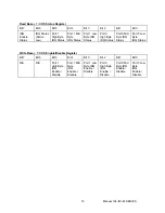
Address Base + 7 is used to control and monitor Change-of-State IRQs. COS IRQs are enabled/disabled
on 8 bit boundaries (Port’s Low, Middle, and/or High byte). To enable COS IRQs, write a “1” to the bit
corresponding to the Port’s Low, Middle and/or High byte. The “Write Base + 7” table describes which bits
enable each byte. Writing “0” to the bit will disable COS IRQs for that byte. A read from bit 7 will show a
“1” if one or more of the COS IRQs have been enabled.
Once COS IRQs have been enabled for the byte(s), a change of input level (low-to-high or high-to-low)
within that byte(s) will set the IRQ latch. After an IRQ is generated, bit 6 of Base + 7 will be set Low (“0”),
which can be used to confirm that a shared interrupt was generated by this board. Also, bits 0-5 will be
set High (“1”) depending upon which byte(s) the COS occurred on. Any read of Base + 7 will clear the
IRQ latch, return bit 6 to it’s High (“1”) state, and return bits 0-5 to their Low (“0”) state. For more on
reading Base + 7 refer to the “Read Base + 7” table.
Please note: Enabling or Disabling IRQs does not clear the IRQ latch. If you disable IRQs while one is
pending, it is still required to read from Base + 7 to clear the pending IRQ.
Manual 104-IDI-48 SERIES
14


