background image


Notice


The information in this document is provided for reference only. ACCES does not assume any liability 
arising out of the application or use of the information or products described herein. This document may 
contain or reference information and products protected by copyrights or patents and does not convey 
any license under the patent rights of ACCES, nor the rights of others. 
  
IBM PC, PC/XT, and PC/AT are registered trademarks of the International Business Machines 
Corporation. 
  
Printed in USA. Copyright 2006 by ACCES I/O Products Inc, 10623 Roselle Street, San Diego, CA 
92121. All rights reserved. 


WARNING!!


ALWAYS CONNECT AND DISCONNECT YOUR FIELD CABLING WITH 

THE COMPUTER POWER OFF. ALWAYS TURN COMPUTER POWER 

OFF BEFORE INSTALLING A CARD. CONNECTING AND 

DISCONNECTING CABLES, OR INSTALLING CARDS INTO A SYSTEM 

WITH THE COMPUTER OR FIELD POWER ON MAY CAUSE DAMAGE 

TO THE I/O CARD AND WILL VOID ALL WARRANTIES, IMPLIED OR 

EXPRESSED.


Manual 104-IDI-48 SERIES 

2

Содержание 104-IDI-48 Series

Страница 1: ...ess underutilized and idle equipment along with credit for buybacks and trade ins Custom engineering so your equipment works exactly as you specify Critical and expedited services Leasing Rentals Demos In stock Ready to ship TAR certified secure asset solutions Expert team I Trust guarantee I 100 satisfaction All trademarks brand names and brands appearing herein are the property of their respecti...

Страница 2: ...10623 Roselle Street San Diego CA 92121 858 550 9559 FAX 858 550 7322 contactus accesio com www accesio com MODEL 104 IDI 48 SERIES USER MANUAL File m104 idi 48 A1d ...

Страница 3: ...thers IBM PC PC XT and PC AT are registered trademarks of the International Business Machines Corporation Printed in USA Copyright 2006 by ACCES I O Products Inc 10623 Roselle Street San Diego CA 92121 All rights reserved WARNING ALWAYS CONNECT AND DISCONNECT YOUR FIELD CABLING WITH THE COMPUTER POWER OFF ALWAYS TURN COMPUTER POWER OFF BEFORE INSTALLING A CARD CONNECTING AND DISCONNECTING CABLES O...

Страница 4: ...warranty Warranty commences with equipment shipment Following Years Throughout your equipment s lifetime ACCES stands ready to provide on site or in plant service at reasonable rates similar to those of other manufacturers in the industry Equipment Not Manufactured by ACCES Equipment provided but not manufactured by ACCES is warranted and will be repaired according to the terms and conditions of t...

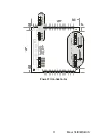
Страница 5: ...tion 8 Figure 2 1 PC 104 Key Information 9 Chapter 3 Option Selection 10 Figure 3 1 Option Selection Map 11 Chapter 4 Address Selection 12 Table 4 1 Standard Address Assignments for Standard Computers 12 Table 4 2 Jumper Selection Example 13 Chapter 5 Programming 14 Chapter 6 Connector Pin Assignments 16 Manual 104 IDI 48 SERIES 4 ...

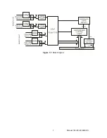
Страница 6: ...er the model number provides a means to automatically interrupt the host computer in real time When one or more input bits change state a PCI interrupt is generated That interrupt in turn can be used by your application program to initiate a poll of the inputs then signal appropriate alarms and or initiate a scan of other I O points that have not been previously activated This can greatly simplify...

Страница 7: ...ating Temperature 0EC to 70EC optional industrial temperature range 40EC to 85EC Storage Temperature 55EC to 150EC Humidity 0 to 95 RH without condensation Board Dimension PC 104 format 3 550 by 3 775 Note on Isolation Opto Isolators and connectors are rated for at least 500V but isolation voltage breakdowns will vary and is affected by factors like cabling spacing of pins spacing between traces o...

Страница 8: ...Figure 1 1 Block Diagram Manual 104 IDI 48 SERIES 7 ...

Страница 9: ...llation The following instructions assume the CD ROM drive is drive D Please substitute the appropriate drive letter for your system as necessary DOS 1 Place the CD into your CD ROM drive 2 Type B to change the active drive to the CD ROM drive 3 Type GLQR JJ to run the install program 4 Follow the on screen prompts to install the software for this board WINDOWS 1 Place the CD into your CD ROM driv...

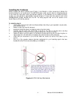
Страница 10: ...ess according to your application requirements as mentioned above 2 Remove power from the PC 104 stack 3 Assemble standoff hardware for stacking and securing the boards 4 Carefully plug the board onto the PC 104 connector on the CPU or onto the stack ensuring proper alignment of the pins before completely seating the connectors together 5 Install I O cables onto the board s I O connectors and proc...

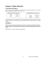
Страница 11: ...C signals as described previously and must be used when AC inputs are applied If you believe an input may be electrically noisy install the jumper to avoid false readings INTERRUPTS Select the desired interrupt level by installing a jumper at one of the locations marked IRQxx If IRQs are enabled in software an interrupt latch is set by the board when an Isolated Digital Input bit changes state A f...

Страница 12: ...ADDRESS 0x300 P1 P2 FILTER SELECT JUMPERS Figure 3 1 Option Selection Map Manual 104 IDI 48 SERIES 11 ...

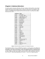
Страница 13: ...EGA 2C0 2CF EGA 2D0 2DF EGA 2E0 2E7 GPIB AT 2E8 2EF Serial Port 2F8 2FF Serial Port 300 30F Prototype Board 310 31F Prototype Board 320 32F Hard Disk XT 370 377 Floppy Controller 2 378 37F Parallel Printer Port 1 380 38F SDLC 3A0 3AF SDLC 3B0 3BB Monochrome Display Printer 3BC 3BF Parallel Printer Port 2 3C0 3CF VGA EGA 3D0 3DF CGA 3E8 3EF Serial Port 3F0 3F7 Floppy Diskette Controller 3F8 3FF Ser...

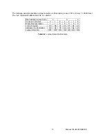
Страница 14: ...ents address lines A2 A1 and A0 Base Address in Hex Code 3 0 0 Conversion Factors 2 1 8 4 2 1 8 Binary Representation 1 1 0 0 0 0 0 Jumper Legend A9 A8 A7 A6 A5 A4 A3 Address Line Controlled A9 A8 A7 A6 A5 A4 A3 Jumper Selection OFF OFF ON ON ON ON ON Table 4 2 Jumper Selection Example Manual 104 IDI 48 SERIES 13 ...

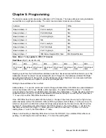
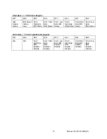
Страница 15: ...hrough 50 as shown in Chapter 6 connector pin assignments Writing to these addresses has no effect Address Base 7 is used to control and monitor Change of State IRQs COS IRQs are enabled disabled on 8 bit boundaries Port s Low Middle and or High byte To enable COS IRQs write a 1 to the bit corresponding to the Port s Low Middle and or High byte The Write Base 7 table describes which bits enable ea...

Страница 16: ...High Byte IRQ Status Port 0 Mid Byte IRQ Status Port 0 Low Byte IRQ Status Write Base 7 COS Enable Disable Register Bit 7 Bit 6 Bit 5 Bit 4 Bit 3 Bit 2 Bit 1 Bit 0 N A N A Port 1 High Byte IRQ Enable Disable Port 1 Mid Byte IRQ Enable Disable Port 1 Low Byte IRQ Enable Disable Port 0 High Byte IRQ Enable Disable Port 0 Mid Byte IRQ Enable Disable Port 0 Low Byte IRQ Enable Disable Manual 104 IDI 4...

Страница 17: ...GND 2 NC 3 Bit 0 A 4 Bit 0 B 5 Bit 1 A 6 Bit 1 B 7 Bit 2 A 8 Bit 2 B 9 Bit 3 A 10 Bit 3 B 11 Bit 4 A 12 Bit 4 B 13 Bit 5 A 14 Bit 5 B 15 Bit 6 A 16 Bit 6 B 17 Bit 7 A 18 Bit 7 B 19 Bit 8 A 20 Bit 8 B 21 Bit 9 A 22 Bit 9 B 23 Bit 10 A 24 Bit 10 B 25 Bit 11 A 26 Bit 11 B 27 Bit 12 A 28 Bit 12 B 29 Bit 13 A 30 Bit 13 B 31 Bit 14 A 32 Bit 14 B 33 Bit 15 A 34 Bit 15 B 35 Bit 16 A 36 Bit 16 B 37 Bit 17 ...

Страница 18: ...ve us some feedback please email us at manuals accesio com Please detail any errors you find and include your mailing address so that we can send you any manual updates 10623 Roselle Street San Diego CA 92121 Tel 858 550 9559 FAX 858 550 7322 www accesio com Manual 104 IDI 48 SERIES 17 ...

Страница 19: ...quipment Have surplus equipment taking up shelf space We ll give it a new home Learn more Visit us at artisantg com for more info on price quotes drivers technical specifications manuals and documentation Artisan Scientific Corporation dba Artisan Technology Group is not an affiliate representative or authorized distributor for any manufacturer listed herein We re here to make your life easier How...

Отзывы: