


SM01P
22
12
INITIAL POWER UP AND MOTOR ROTATION
DANGER!
Hazard of electrical shock! Wait three minutes after disconnecting incoming power
before servicing drive . Capacitors retain charge after power is removed .
STOP!
•
DO NOT connect incoming AC power to output terminals U, V, and W or
terminals B+, B-! Severe damage to the drive will result . Do not continuously
cycle input power to the drive more than once every two minutes . Damage to
the drive will result .
•
Severe damage to the drive can result if it is operated after a long
period of storage or inactivity without reforming the DC bus capacitors!
Refer to Section 6 .1, Installation After a Long Period of Storage
Before attempting to operate the drive, motor, and driven equipment, be sure all procedures
pertaining to installation and wiring have been properly followed .
Disconnect the driven load from the motor . Verify that the drive input terminals (L1 and
L2/N, or L1, L2, and L3) are wired to the proper input voltage per the nameplate rating
of the drive .
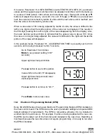
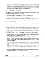
Energize the incoming power line . The LED display will flash a three digit number (320
in the example below) that identifies the parameter version contained in the drive . The
display should then read “- - -”, which indicates that the drive is in a STOP condition . This
is shown below:
Apply input power
Display then reads "- - -"
Display flashes parameter
version (300-399)
Follow this 4-step procedure to check the motor rotation . This procedure assumes that
the drive has been powered up for the first time, and that none of the parameters have
been changed .
1 . Use the
button to decrease the speed setpoint to 00 .0 Hz . The left decimal point
will illuminate as the speed setpoint is decreased . If the
button is held down, the
speed setpoint will decrease by tenths of Hz until the next whole Hz is reached, and
then it will decrease by one Hz increments . Otherwise, each push of the
button will
decrease the speed setpoint by a tenth of a Hz .
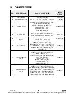
Once 00 .0 Hz is reached, the display will toggle between “00 .0” and “- - -”, which
indicates that the drive is in a STOP condition with a speed setpoint of 00 .0 Hz .
2 . Give the drive a START command . This can be done using one of several wiring
methods described in Section 11, SCL/SCM CONTROL WIRING DIAGRAMS . Once
the START command is issued, the display will read “00 .0”, indicating that the drive
is in a RUN condition with a speed setpoint of 00 .0 Hz .
Phone: 800.894.0412 - Fax: 888.723.4773 - Web: www.clrwtr.com - Email: [email protected]


