Above
Air
™
MissionCritical
™
A/C’s
AboveAir
Technologies
(MC22-L12)
12
Overflow Safety Float Switches:
The system shall be provided with a fac
-
tory installed float type condensate over
-
flow safety switches. The circuit shall be
designed to shut down all system water
producing operations in the event of an
overflow condition.
2.1.3.1 Main Power, Non-Fused
Disconnect
(VC_ Evap Section)
The indoor evaporator section shall be
provided with a factory installed main
power non-fused disconnect. The dis
-
connect shall be NEMA rated for indoor
or outdoor installation as required.
2.1.4 Evap Blower/Motor
The evaporator blower assembly shall
be a backward-inclined direct-drive
centrifugal impeller with variable speed
EC (electronically communicated) motor.
The blower shall be designed for ____
CFM @ ____ inches external static pres
-
sure (e.s.p.)
2.1.5 Air Patterns
Up-Flow (UF) Down-Flow (DF)
2.1.5.1
Up-Flow Air Pattern
2.1.5.1.1
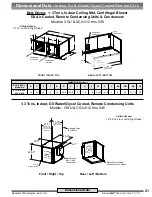
UF: Front-Free Return
The system shall be configured for up-
flow evaporator air pattern with front-free
return and top discharge.
(Refer to
Plenum Discharge Box Options.)
2.1.5.1.2
UF: Rear-Ducted Return
The system shall be configured for
up-flow evaporator air pattern with rear
ducted return and top discharge.
1.0 General
1.1 Summary
These specifications describe the re
-
quirements for a vertical floor mounted
packaged (or split) precision air condi
-
tioner. The system shall be designed to
control space temperature and humidity.
The air conditioning manufacturer shall
design and furnish all equipment in the
quantities and configurations shown on
the project plans and specifications.
The system shall be provided by Above
-
Air Technologies in Frederick, Maryland,
USA. The system shall be listed by
Intertek (ETL Semko), Inc. to conform
with UL Std 1995 and be certified to
CAN/CSA Std C22.2 No. 236 (Control
No. 3091370). The system shall be NYC
MEA229-06-E and Chicago Code Ap
-
proved. The system model number shall
be _____________.
1.2 Design Requirements
The system shall be an AboveAir Tech
-
nologies VK-MissionCritical™ brand fac
-
tory assembled and tested. The system
shall be designed for indoor installation.
The system shall have a total cooling
capacity of ______ BTU/H, and a sen
-
sible cooling capacity of ______ BTU/H,
based on an entering air condition of
______ °F DB, and ______ °F WB,
______ % RH.
The evaporator section shall be designed
for _____ Volt, ______ Phase, _____
Hertz main power supply. The remote
condensing unit section (if applicable)
shall be designed for _____ Volt, ______
Phase, _____ Hertz main power supply.
1.3 Submittals
Submittals shall be provided after manu
-
facturer’s receipt of a written purchase
order and shall include: Detailed Perfor
-
mance and Electrical Data; Guide Speci
-
fications; and Dimensional Drawings.
1.4 Quality Assurance
The system shall be factory run tested
prior to shipment. Testing shall include,
but shall not be limited to: “HiPot” Test
(2 times rated voltage plus 1000 volts,
per UL 1995 testing requirements). The
system shall be designed and manufac
-
tured according to world class quality
standards.
2.0 Products
2.1 Standard Features /
All Systems
2.1.1 Cabinet
The cabinet chassis and access panels
shall be powder-coat painted heavy
gauge galvanneal steel for decor match
-
ing and corrosion resistance. Cabinet
access panels shall rest in recessed
pockets designed for minimum air leak
-
age. The cabinet and access panels
shall be lined with 2 lb/ft
2
high density
sound and thermal insulation and sealed
with self-extinguishing gasketing con
-
forming to NFPA 90A and 90B.
2.1.2 Component Access
The unit shall be serviceable through
front access panels with quick-release
quarter-turn fasteners.
2.1.3 Electrical System
General:
The electrical system shall conform to
National Electric Code (NEC) require
-
ments according to UL 1995. The control
circuit shall be a 24 VAC low voltage
circuit.
The electrical system shall include, but
not be limited to the following factory
installed items: main power distribution
block; grounding lug; 24 VAC control
transformer; terminal connections; and
motor controllers with start protection
and circuit breakers for blower motors,
compressors and each electric heater
stage (if applicable).
Packaged Systems:
(single point
power)
Self-Contained systems shall be
designed for single point main power
connection.
Split DX Systems:
(separate power)
Split systems shall require separate main
power supplies to the evaporator and
condensing unit sections. The evapora
-
tor and condensing unit sections shall be
electrically interlocked by a field wired 24
volt control signal.
Guide Specifications
Guide Specifications -
MC
-
2x2
™
Mission
Critical
(1-3 Tons)


