


11
The Wallbox eM4 Single at a glance
View from above and below
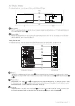
The following illustration shows the top and bottom of the Wallbox eM4 Single.
Top
Bottom
8
Key opening
Insert the supplied key through this opening and push it upwards to open the internal lock on the left-hand side of the housing
cover (see also below, RCCB flap
12
).
9
Housing inlets
The inlets on the top and bottom can be opened with combination pliers or a similar tool and are used for inserting the power
and data cable from above or below (see page 25).
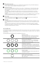
Interior and side view
The following illustration shows the Wallbox eM4 Single with the housing cover open and from the right-hand side.
16 mm 85 mm
Interior view / electronics
Right-hand side
10
Housing
The wallbox housing integrates the power module
15
and the additional electronic components for communication in a group.
The wallbox is securely fastened at the installation location by means of the suspension points
1
and the attachment points
2
and
7
.
11
Terminal block
Directly in front of the supply cable area
3
is the terminal block for connecting the power line: The connection pattern is shown
on the communication module
14
. In a group installation, the connection diagram must be adapted for each wallbox to avoid a
phase imbalance (see “Electrical connection of the wallbox” on page 28).
12
RCCB flap
The RCCB flap protects the RCCB of the power module
15
and is locked and unlocked using the key supplied. The locking mech-
anism is also used to lock/unlock the right-hand side of the housing cover
4
(see also above, Key opening
8
).
Front
Содержание Wallbox eM4 Single
Страница 1: ...Wallbox eM4 Single Installation manual Article No 0301504_EN_a...
Страница 66: ...66 Appendix R ckseite ABL Configuration App...
Страница 67: ...67...


