BIOS Setup
3-17
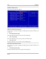
Wake-Up by Ring:
When set to [Enabled], telephone calls coming through an external or internal modem
will power-on your system.
WakeUp by Alarm:
When set to [
Enabled
], you can set the date and time you would like the Soft-Off PC
to power-on in the “
Date (of Month) Alarm
” and “
Time (hh:mm:ss) Alarm
” items.
However, if the system is being accessed by incoming calls or the network (Resume
On Ring/LAN) prior to the date and time set in these items, the system will give
priority to the incoming calls or network instead.
Date (of Month) Alarm
[0]:
This option power-on the system everyday according to the time set in the “Time
(hh:mm:ss) Alarm” item.
[1-31]:
This option selects a date you would like the system to power-on. The system
will power-on on the date set, and the time set in the “Time (hh:mm:ss) Alarm” item.
Resume Time (hh:mm:ss)
This item sets the time you would like the system to power-on.
POWER ON Function:
This item selects the way you want your system to power on.
[Password]:
Use a password to power on the system, select this option then press
<Enter>. Enter your password. You can enter up to 5 characters. Type in exactly the
same password to confirm, and then press <Enter>.
[Hot KEY]:
Use any of the function keys between <F1> to <F12> to power on the
system.
[Mouse Left]:
Double click the mouse left button to power on the system.
[Mouse Right]:
Double click the mouse right button to power on the system.
[Any KEY]:
Use any keyboard keys to power on the system.
[BUTTON ONLY]:
Use only the power button to power on the system.
[Keyboard 98]:
Use the power-on button on the “Keyboard 98” compatible keyboard
to power on the system.
NOTE:
To enable this “Power On” function, the wake-up header of [USB-PWR1]
must be set to [Enabled] position. Please refer to the configuration of “Wake-up
Header” [USB-PWR1] in section 2-4, chapter 2.
User’s Manual
Содержание SV-1A
Страница 1: ...SV 1A AMD Athlon 64 Server Board Socket 939 User s Manual Rev 1 00...
Страница 7: ...Introduction 1 3 1 2 Layout User s Manual...
Страница 23: ...Hardware Setup 2 15 2 3 12 Low Pin Count Connection Header J1 Reserved for internal testing User s Manual...
Страница 34: ...3 8 Chapter 3 3 3 Advanced Chipset Features DRAM Configuration Click Enter key to enter its submenu SV 1A...
Страница 37: ...BIOS Setup 3 11 3 4 Integrated Peripherals OnChip IDE Device Click Enter key to enter its submenu User s Manual...
Страница 47: ...BIOS Setup 3 21 3 7 PC Health Status User s Manual...

