background image

Installing the VGA Drivers for the Windows

®

 NT 4.0 Server / Workstation

E-1

User’s Manual

Appendix E Installing the VGA Drivers for the

Windows

®

 NT 4.0 Server /

Workstation

In this section we will show you how to install the VGA drives to your Windows

®

 NT 4.0

Server/Workstation operating system. All screen shots are from Windows

®

 NT 4.0 server

version. Before you install the VGA drivers, please install Windows

®

 NT 4.0 Service Pack 4

(or latest version) first. Then you can install the VGA drivers.

Note E-1

Details of the Windows

®

 NT 4.0 Server/Workstation operating system are not

mentioned in this manual. If you have any problems with the settings, operating or
installing Windows

®

 NT 4.0 Server/Workstation, please refer to your Windows

®

 NT 4.0

Server/Workstation user's manual or other databases provided by Microsoft

®

Corporation.

Note E-2

For Windows

®

 NT 4.0 Server/Workstation operating system, you don't need to install

the INF Installation Utility. But you have to install the Windows

®

 NT 4.0 Service Pack 4

(or latest version) first.

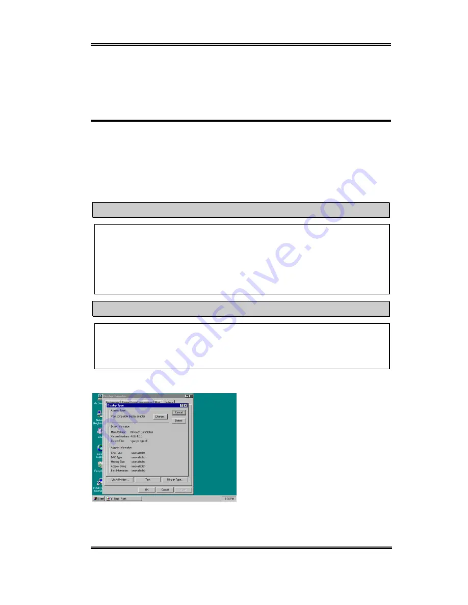
Go to check your "

Display Properties

".

You will see that the graphics information is
unavailable.

Содержание SL6

Страница 1: ...cidental or consequential damages arising from any defect or error in this manual or product Product names appearing in this manual are for identification purpose only and trademarks and product names or brand names appearing in this document are the property of their respective owners This document contains materials protected under International Copyright Laws All rights reserved No part of this...

Страница 2: ......

Страница 3: ...THE BIOS 3 1 CPU SETUP SOFT MENU II 3 4 3 2 STANDARD CMOS FEATURES SETUP MENU 3 12 3 3 ADVANCED BIOS FEATURES SETUP MENU 3 16 3 4 ADVANCED CHIPSET FEATURES SETUP MENU 3 21 3 5 INTEGRATED PERIPHERALS 3 25 3 6 POWER MANAGEMENT SETUP MENU 3 32 3 7 PNP PCI CONFIGURATIONS SETUP MENU 3 41 3 8 PC HEALTH STATUS 3 44 3 9 LOAD FAIL SAFE DEFAULTS 3 46 3 10 LOAD OPTIMIZED DEFAULTS 3 46 3 11 SET PASSWORD 3 47 ...

Страница 4: ...TATION APPENDIX I INSTALLING THE VGA DRIVER FOR THE WINDOWS 2000 SERVER WORKSTATION APPENDIX J INSTALLING THE AUDIO DRIVER FOR THE WINDOWS 2000 SERVER WORKSTATION APPENDIX K ATA INSTALLATION FOR THE WINDOWS 2000 SERVER WORKSTATION APPENDIX L BIOS FLASHING USER INSTRUCTIONS APPENDIX M HARDWARE MONITORING FUNCTION INSTALLING THE WINBOND HARDWARE DOCTOR UTILITY APPENDIX N INSTALLATION GUIDE FOR SUSPE...

Страница 5: ...ce supporting digital display and TV Out are options The SL6 also has an integrated AC 97 2 1 CODEC onboard This CODEC is complete with a H W Sound Blaster Pro AC 97 digital audio controller that gives you the best sound quality and compatibility The chipset includes integrated 2X 3D Graphics Acceleration For those wanting even greater graphics performance an AGP slot is included on the board The ...

Страница 6: ...3 66 and feature specification devices 3 Graphics Chipset integrated 2X 3D graphics acceleration Support 4MB display Cache AIMM AGP In line Memory Module 4 Memory Three 168 pin DIMM sockets support SDRAM module Supports up to 512MB MAX 64 128 256MB SDRAM Support 100MHz 133MHz SDRAM interface No 66Mhz support 5 Audio AC 97 Digital Audio controller integrated AC 97 Audio CODEC on board Audio driver ...

Страница 7: ...Monitoring Including Fan speed Voltages CPU and System temperature and one thermal header for other devices temperature monitoring Keyboard and Mouse Power On Built in Wake on LAN Open Chassis header Built in IrDA TX RX header Digital Video out interface adds support digital display or TV out Option PC99 Compliant Supports Wake On LAN Modem but your ATX power supply 5V standby power must be able t...

Страница 8: ...1 4 Chapter1 SL6 1 3 Layout Diagram Figure 1 2 SL6 Motherboard component location ...

Страница 9: ...Introduction of SL6 Features 1 5 User s Manual 1 4 The System Block Diagram Figure 1 3 System diagram of the INTEL 815 Chipset ...

Страница 10: ...1 6 Chapter1 SL6 ...

Страница 11: ... the Motherboard to the Chassis 2 2 Installation of the Pentium III Celeron CPU 2 3 Installing System Memory 2 4 Connectors Headers and Switches Before Proceeding with the Installation Before you install or unplug any connectors or add on cards please remember to turn the ATX power supply switch off fully turn the 5V standby power off or disconnect the power cord Otherwise you may cause the mother...

Страница 12: ...unable to do this should you attach the board with spacers Take a careful look at the motherboard and you will see many mounting holes on it Line these holes up with the mounting holes on the base If the holes line up and there are screw holes this means you can attach the motherboard with studs If the holes line up and there are only slots this means you can only attach the motherboard with space...

Страница 13: ...B surface as the circuit wire may be too near the hole Be careful Do not let the screw contact the printed circuit wire or parts on the PCB that are near the fixing hole Otherwise it may damage the board or cause board malfunctioning 2 2 Installation of the Pentium III CPU The installation method for the CPU is printed on the package of the retention mechanism that comes with the motherboard You c...

Страница 14: ...28MB 8MB 512MB Bank 2 3 DIMM2 8MB 16MB 32MB 64MB 128MB 8MB 512MB Bank 4 5 DIMM3 8MB 16MB 32MB 64MB 128MB 8MB 512MB Total System Memory 8MB 512MB Generally installing SDRAM modules to your motherboard is an easy thing to do You can refer to figure 2 3 to see what a 168 pin PC100 PC133 SDRAM module looks like DIMMs may be snapped directly into the socket Note Certain DIMM sockets have minor physical...

Страница 15: ...ne way only Firmly press the DIMM module into the DIMM socket making certain the module is completely seated in the DIMM socket Step 6 Once the DIMM module has been installed the installation is complete and the computer s cover can be replaced Or you can continue to install other devices and add on cards that are mentioned in the following section Note When you install a DIMM module fully into th...

Страница 16: ...ere and tell you how to connect them Please pay attention and read the entire section for necessary information before attempting to finish all of the hardware installation inside the computer chassis Figure 2 5 shows you all of the connectors and headers that we ll discuss in the next section you can use this diagram to visually locate each connector and header we describe All connectors headers ...

Страница 17: ...e ATX power supply firmly into the ATXPR1 connector ensuring that you have a good connection Note Watch the pin position and the orientation 2A 2B 2C FAN1 FAN2 FAN3 header Attach the connector from the individual CPU fan to the header named FAN1 The connector from the chassis fan should be attached to the header FAN3 and the connector from the power fan to FAN2 You must attach the CPU fan to the p...

Страница 18: ... position and the orientation 4 WOL1 Wake on LAN Header If you have a network adapter that supports this feature then you can connect the specific cable from the network adapter to this header This feature lets you wake up your computer via remote control through a local area network You may need a specific utility to control the wake up event such as the PCnet Magic Packet utility or other simila...

Страница 19: ...he orientation 6 RT2 Thermister The RT2 is a thermistor used to detect the system environmental temperature It may also be called a system temperature detector You can attach one end of the two threaded thermal cable that comes with the motherboard to the RT2 header then tape the other end of the thermal cable on the CPU s heat sink Generally speaking the location you tape the thermistor should be...

Страница 20: ...lly by SW3 SW4 SW3 SW4 on 66MHz SW3 off SW4 on 100MHz SW3 SW4 off 133MHz 3 SW5 on SW6 off This is the default setting 4 SW7 This is to enable or disable the On Board Codec Set on to disable 5 SW8 This is to set the SoftMenu or None SoftMenu Set on to None SoftMenu 9 CCMOS1 CMOS Discharge Jumper The jumper CCMOS discharges CMOS memory When you install the motherboard make sure this jumper is set fo...

Страница 21: ... Figure 2 7 shows you the functions of PN1 and PN2 Figure 2 7 The definition of PN1 and PN2 pins PN1 Pin 1 2 3 4 5 Power LED Headers There is a specific orientation for pins 1 through 3 Insert the three threaded power LED cable to pins 1 3 Check to make sure the correct pins go to the correct connectors on the motherboard If you install them in the wrong direction the power LED light will not illu...

Страница 22: ...rdware Note If the ACPI function in the BIOS setup is enabled this function will not work PN2 Pin 1 2 Hardware Reset Switch Header Attach the cable from the case s front panel reset switch to this header Press and hold the reset button for at least one second to reset the system PN2 Pin 4 5 6 7 Speaker Header Attach the cable from the system speaker to this header PN2 Pin 9 10 Suspend LED Header I...

Страница 23: ...14 Suspend signal PN2 PIN 14 No connection Let s now see the I O connectors that the SL6 uses and what their functions are 11 FDC1 Connector This 34 pin connector is called the floppy disk drive connector You can connect a 360K 5 25 1 2M 5 25 720K 3 5 1 44M 3 5 or 2 88M 3 5 floppy disk drive You can even connect a 3 Mode floppy disk drive a 3 1 2 drive used in Japanese computer systems A floppy di...

Страница 24: ...st connector on the motherboard that is the IDE1 connector on the motherboard Secondary refers to the second connector on the motherboard that is the IDE2 connector on the motherboard Two hard disks can be connected to each connector The first HDD is referred to as the Master and the second HDD is referred to as the Slave For performance issues we strongly suggest you don t install a CD ROM drive ...

Страница 25: ...tor on the other end and a gray connector in the middle In addition line 34 on the cable should be notched or cut this may be difficult to see Ultra ATA 66 is backwards compatible with all Ultra ATA 33 systems but it will be limited in its transfer mode to the Ultra ATA 33 Ultra DMA Mode 2 33 Mbytes sec or PIO Mode 4 16 6 Mbytes sec Ultra ATA 66 hard drives are 100 percent backward compatible with...

Страница 26: ...ted on the body of the plastic This fits into the matching slot on the mating plugs on the motherboard and the drives thus assuring positive mating pin 1 to pin 1 The red line on the cable should be aligned with pin 1 On the drives this will result in the red line facing the power connector Attach the BLUE connector to the appropriate 40 pin IDE plug on the motherboard Attach the BLACK connector t...

Страница 27: ...pper PS 2 Mouse Connector Attach a PS 2 mouse to this 6 pin Din connector USB Port Connectors This motherboard provides two USB ports Attach the USB connector from the individual device to these connectors You can attach USB devices such as a scanner digital speakers monitor mouse keyboard hub digital camera joystick etc to one of each of the USB connectors You must make sure your operating system...

Страница 28: ...cation protocol to this connector You can decide which external device you want to connect to COM1 The COM port can only have one device connected at a time Parallel Port Connector This parallel port is also called an LPT port because it usually connects to the printer You can connect other devices that support this communication protocol like an EPP ECP scanner etc ...

Страница 29: ...ker You must use a speaker that has a built in amplifier Otherwise you may not be able to hear any sound or only a small volume of sound from the speaker Line In Connector You can connect the TV adapter audio output signal or external audio sources like a CD walkman video camcorder VHS recorder audio output signal plug to this connector Your audio software can control the input level for the line ...

Страница 30: ...plugs to this connector Please refer to the further connection notes of the device s user s manual for further detailed information Note This chapter contains many color drawing diagram and photos we strongly recommend you to read this chapter using the PDF file that is included on the CD It will provide you with greater clarity ...

Страница 31: ... produce errors the computer will crash and sometimes you will not even be able to boot the computer after it has crashed We recommend that you do not change the parameters inside the BIOS unless you are very familiar with them If you are not able to boot your computer anymore please refer to the section Erase CMOS data in Chapter 2 When you start the computer the BIOS program controls it The BIOS...

Страница 32: ...irst see a short description of the function keys you may use here Press Esc to quit the BIOS Setup Press up down left right to choose in the main menu the option you want to confirm or to modify Press F10 when you have completed the setup of BIOS parameters to save these parameters and to exit the BIOS Setup menu Press Page Up Page Down or keys when you want to modify the BIOS parameters for the ...

Страница 33: ...ured This memory is passive You can read its data and you can also store data in it But this memory has to be powered by a battery in order to avoid any loss of its data when the computer is turned off Since you may have to change the CMOS battery when it is out of power and if doing so you will lose all CMOS data we recommend that you write down all the parameters of your hardware or to put a lab...

Страница 34: ...ng any jumpers or switches The CPU must be setup according to its specifications You can press F1 at any time for help Figure 3 2 CPU SOFT MENU II CPU Name Is Intel Celeron MMX Intel Pentium III MMX CPU Operating Speed This option sets the CPU speed In this field the CPU speed is indicated like this CPU speed External clock Multiplier factor select the CPU speed according the type and the speed of...

Страница 35: ...eering testing not for normal applications If you use non specification settings for normal operation your system may not be stable and may effect system reliability Also we do not guarantee the stability and compatibility for settings that are not within specification and any damage of any elements on the motherboard or peripherals is not our responsibility Ext Clock PCI 66MHz 2 3 1 default 100MH...

Страница 36: ... as 100MHz 1 1 1 3 Additionally for the working value of the CPU in this case a Pentium III 500MHz you calculate it like this CPU working value FSB 100MHz x 5 500MHz proper value for this CPU Also the AGP value is derived from the PCI value so that AGP value PCI value 33MHz x 2 or 4 66MHz or 132MHz proper value for AGP bus For a 2x AGP it works at double the speed of the PCI bus and four times for...

Страница 37: ...ble above to get the working values you are taking the 3 3 1 numbers and multiplying by 3 then dividing by 3 For another example in the table you have 138MHz 4 3 1 divided by 4 You can look at it like this 138MHz 1 3 4 1 4 Each multiplied times 4 will give you the same value as 138MHz 4 3 1 needing to be divided by 4 again So that for the FSB you have 4 divided by 4 giving you a value of 1 so that...

Страница 38: ... Pentium III Coppermine using FC PGA 100MHz 3 3 1 each divided by 3 100MHz 100MHz 33MHz or a CPU rated for 133MHz FSB such as a Pentium III Coppermine using FC PGA 133MHz 4 3 1 each divided by 4 133MHz 100MHz 33MHz Note the various components and their corresponding bus speeds should still work fine nonetheless going too far out of spec may cause system damage or malfunction System performance wil...

Страница 39: ...ly use its standard parameters to boot You can then enter the BIOS Setup again and set up the CPU clock If you can t enter the BIOS setup you must try turning the system on a few times 3 4 times or press INSERT when turning on and the system will automatically use its standard parameters to boot You can then enter BIOS SETUP again and set up the new parameters When you change your CPU This motherb...

Страница 40: ...is enabled the option Core Voltage will show the current voltage setting that is defined by the CPU and this will not be changeable We recommend using this CPU default setting and not changing it unless the current CPU type and voltage setting can not be detected or is not correct User Define This option lets the user select the voltage manually You can change values of the Core Voltage option lis...

Страница 41: ...D settings Figure 3 3A Standard CMOS Setup Screen Shot Date mm dd yy You can set the date in this item month mm date dd and year yy Time hh mm ss You can set the time in this item hour hh minute mm and second ss IDE Primary Master Slave and IDE Secondary Master Slave These items have a sub menu to let you choose further options You can refer to figure 3 4 to check what options are available ...

Страница 42: ...not read write The basic step in using a HDD is to make a HDD low level format then run FDISK and then FORMAT the drive Most current HDDs have already been subjected to low level format at the factory so you can probably skip this operation Remember though the primary IDE HDD must have its partition set to active within the FDISK procedure If you are using an old HDD that is already formatted auto...

Страница 43: ...rts hard disks of up to 528MB or less This mode directly uses positions indicated by Cylinders CYLS Heads and Sectors to access data LBA Logical Block Addressing mode The earlier LBA mode can support HDD capacities of up to 8 4GB and this mode uses a different method to calculate the position of disk data to be accessed It translates Cylinders CYLS Heads and Sectors into a logical address where da...

Страница 44: ...he maximum number you can enter is 255 Precomp The minimum number you can enter is 0 the maximum number you can enter is 65536 Warning Setting a value of 65536 means no hard disk exists Landing Zone This is a non data area on the disk s inner cylinder where the heads can rest when the power is turned off The minimum number you can enter is 0 the maximum number you can enter is 65536 Sector The min...

Страница 45: ... Mode floppy drive Video You can select the VGA modes for your video adapter four options are available EGA VGA CGA 40 CGA 80 MONO The default setting is EGA VGA Halt On You can select which type of error will cause the system to halt Five options are available All Errors No Errors All But Keyboard All But Diskette All But Disk Key You can see your system memory list in the lower right box it show...

Страница 46: ... options for that item Attention Advanced BIOS Features Setup Menu has already been set for maximum operation If you do not really understand each of the options in this menu we recommend you use the default values Figure 3 4A Advanced BIOS Features Setup Upper Screen Figure 3 4B Advanced BIOS Features Setup Lower Screen ...

Страница 47: ...uter malfunction or crash if the system speed is too high In this case you should disable this feature The default setting is Enabled CPU Level 2 Cache This item is used to enable or to disable the CPU level 2 cache When the external cache is enabled it will speed up memory access and the system will work faster The default setting is Enabled CPU L2 Cache ECC Checking This item is used to enable o...

Страница 48: ...ed The default setting is Enabled This setting allows the BIOS to try three kinds of boot devices that are set from the above three items Swap Floppy Drive This item can be set as Enabled or Disabled The default setting is Disabled When this feature is enabled you don t need to open the computer case to swap the position of floppy disk drive connectors Drive A can be set as drive B and drive B can...

Страница 49: ...seconds Four options are available 250 500 750 1000 Back to 250 The default setting is 250 Security Option This option can be set to System or Setup The default setting is Setup After you have created a password through PASSWORD SETTING this option will deny access to your system System or modification of computer setup BIOS Setup by unauthorized users SYSTEM When you choose System a password is r...

Страница 50: ...t Non OS2 The default setting is Non OS2 Report No FDD For WIN 95 When using Windows 95 without a floppy drive please set this item to Yes Otherwise set it to No The default setting is No Delay IDE Initial Secs This item is used to support some old models or special types of hard disks or CD ROMs They may need a longer amount of time to initialize and prepare for activation Since the BIOS may not ...

Страница 51: ...ry well use default values i e use the LOAD SETUP DEFAULTS option The only time you might consider making any changes is if you discover that data is being lost while using your system Figure 3 5A Chipset Features Setup Screen You can use the arrow keys to move between the items Use and Enter key to change the values When you have finished setting up the chipset press Esc to go back to the main me...

Страница 52: ...s you insert a timing delay between the CAS and RAS strobe signals used when DRAM is written to read from or refreshed Fast 2 gives faster performance and Slow 3 gives more stable performance This item applies only when synchronous DRAM is installed in the system SDRAM RAS Precharge Time Two options are available 2 and 3 The default setting is 3 This option lets you insert a timing delay between t...

Страница 53: ...ust be enabled to provide PCI 2 1 compliance If you have an ISA card compatibility problem you can try to enable or disable this option for optimal results On Chip Video Window Size Three options are available 64MB 32MB Disabled The default setting is 64MB This option specifies the amount of system memory that can be used by the AGP graphic data AGP Graphics Aperture Size Two options are available...

Страница 54: ...en You can select the paging mode control to open or close RAS to CAS Override Two options are available by CAS LT and Override 2 The default setting is by CAS LT This is the display cache clock period control RAS Timing Two options are available Slow and Fast The default setting is Fast This item controls RAS active to Protegra and refresh to RAS active delay in local memory area RAS Precharge Ti...

Страница 55: ...S Setup 3 25 User s Manual 3 5 Integrated Peripherals In this menu you can change the onboard I O device I O port address and other hardware settings Figure 3 6A Integrated Peripherals Menu Default Screen ...

Страница 56: ...uto Mode 0 Mode 1 Mode 2 Mode 3 Mode 4 The four IDE PIO Programmed Input Output items let you set a PIO mode 0 4 for each of the four IDE devices that the onboard IDE interface supports Modes 0 through 4 provide successively increased performance In Auto mode default setting the system automatically determines the best mode for each device Master Slave Drive Ultra DMA Two options are available Aut...

Страница 57: ...et it to Disabled then the item USB Keyboard Support will also be disabled USB Keyboard Support Two options are available OS and BIOS The default setting is OS If you want USB keyboard use in a DOS environment please set it to BIOS Init Display First Two options are available PCI Slot and Onboard The default setting is PCI Slot When you install additional PCI display cards you can choose either a ...

Страница 58: ... 98 Hot Key Mouse Left Mouse Right Default setting is Button Only Note The mouse wake up function can only be used with the PS 2 mouse not with a mouse that uses the COM port and USB connection Mouse Left Mouse Right means you need to double click the mouse left right button for the computer to power on You also need to note the compatibility issue with your PS 2 mouse Some PS 2 mice cannot wake u...

Страница 59: ...n Three options are available IrDA HPSIR mode ASK IR Amplitude Shift Keyed IR mode Normal The default setting is Normal RxD TxD Active Four options are available Hi Hi Hi Lo Lo Hi Lo Lo The default setting is Hi Lo Set IR transmission reception polarity as High or Low IR Transmission Delay Two options are available Enabled and Disabled The default setting is Enabled Set IR transmission delays 4 ch...

Страница 60: ...default setting is EPP 1 7 When the mode selected for the parallel port mode is EPP the two EPP version options are available ECP Mode Use DMA Two options are available 1 3 The default setting is 3 When the mode selected for the parallel port mode is ECP the DMA channel selected can be Channel 1 or Channel 3 PWRON After PWR Fail This setting lets you set the system action after a power failure Thr...

Страница 61: ...ou choose disable the Midi Port Address then this field is not available Note If you buy the audio adapter and want to replace the use of onboard audio solution you have to disable three items in BIOS Otherwise your audio adapter may not work well These three items are AC 97 Audio set to Disabled Game Port Address set to Disabled Midi Port Address set to Disabled ...

Страница 62: ...mouse and other device These are referred to as Power Management Events In cases where none of these events occur the system enters the power saving mode When one of the controlled events occurs the system immediately returns to normal mode and operates at its maximum speed Power saving modes can be divided into three modes according to their power consumption Doze Mode Standby Mode and Suspend Mo...

Страница 63: ... configure To change the settings use and Enter key 3 After you have configured the power management feature press Esc to go back to the Main Menu We are now going to briefly explain the options in this menu ACPI Function Advanced Configuration and Power Interface ACPI gives the operating system direct control over the power management and Plug and Play functions of a computer ...

Страница 64: ...ined in the BIOS Power management control of individual devices add in cards some add in cards may require an ACPI aware driver video displays and hard disk drives A Soft off feature that enables the operating system to power off the computer Support for multiple wake up events see Table 3 6 1 Support for a front panel power and sleep mode switch Table 3 6 2 describes the system states based on ho...

Страница 65: ... states System S0 state S1 S2 S3 S4 S5 S1 and S3 states are described below The S1 POS State POS means Power On Suspend While the system is in the S1 sleeping state its behavior is as described below The processor is not executing instructions The processor s complex context is maintained Dynamic RAM context is maintained Power Resources are in a state compatible with the system S1 state All Power...

Страница 66: ...e to S0 This transition causes the processor to begin execution at its boot location The BIOS performs initialization of core functions as required to exit an S3 state and passes control to the firmware resume vector Please see the ACPI Specification Rev 1 0 book section 9 3 2 for more details on BIOS initialization From the software point of view this state is functionally the same as the S2 stat...

Страница 67: ...bled the system is set up for maximum power savings Suspend Mode 1 Min HDD Power Down 1 Min Video Off Method Three video off methods are available Blank Screen V H SYNC Blank and DPMS The default is V H SYNC Blank If this setting does not shut off the screen select Blank Screen If your monitor and video card support DMPS standard select DPMS Blank Screen This option only writes blanks to the video...

Страница 68: ...4 Min 8 Min 12 Min 20 Min 30 Min 40 Min 1 Hour The default setting is Disabled 1 Hour 1 Min HDD Power Down Disabled 1 Min 2 Min 3 Min 4 Min 5 Min 6 Min 7 Min 8 Min 9 Hour 10 Min 11 Min 12 Min 13 Min 14 Min 15 Min The default setting is Disabled 15 Min 1 Min Soft Off by PWR BTTN Two options are available Instant Off and Delay 4 Sec The default setting is Instant Off Pressing the power button for mo...

Страница 69: ...ermal Throttling This option is used during Suspend To RAM STR mode It controls the CPU speed as a percentage of regular power Options include 87 5 75 0 62 5 50 0 37 5 25 0 12 5 The default setting is set at 62 5 Resume by Alarm Two options are available Enabled and Disabled Default setting is Disabled The RTC alarm can turn on the system You can set Date of month and Time hour minute and second w...

Страница 70: ...fault setting is Disabled If any secondary IDE master slave I O activity occurs it will cause the computer to re count the time elapsed FDD COM LPT Port Two options are available Enabled and Disabled Default setting is Enabled If any floppy disk COM ports and Parallel port I O activity occurs it will cause the computer to re count the time elapsed PCI PIRQ A D Two options are available Enabled and...

Страница 71: ...l items and it is strongly recommended that only experienced users should make any changes to the default settings Figure 3 11 PnP PCI Configurations Setup Screen Shot PNP OS Installed Two options are available No and Yes Default setting is No Device resource assigned by PnP OS or BIOS Force Update ESCD If you want to clear ESCD data next time you boot up and ask the BIOS to reset the settings for...

Страница 72: ...evices If you select Auto ESCD The IRQ Resources item will be disabled as the BIOS automatically assigns them But if you have trouble in assigning the interrupt resources automatically you can select Manual to set which IRQ and DMA are assigned to PCI ISA PnP or legacy ISA cards Figure 3 12 shows you the screen of IRQ resources Each item has two options PCI Device and Reserved The default setting ...

Страница 73: ...t will cause a hardware conflict This feature is for the operating system which will record and fix the PCI configuration status if you want to change it For the relations between the hardware layout of PIRQ the signals from the 810E chipset INT means PCI slot IRQ signals and devices please refer to the table below Signals PCI slot 1 PCI slot 6 PCI slot 2 PCI slot 3 PCI slot 4 PCI slot 5 PIRQ_0 IN...

Страница 74: ...u select the temperature at which you want the system to send out a warning message to the PC speakers of when the temperature goes beyond either limit You can select the temperatures you want The ranges are from 30 C 86 F to 120 C 248 F default setting is 75 C 167 F All Voltages Fans Speed and Thermal Monitoring These items list the current states of the CPU and environment using RT1 and RT2 to d...

Страница 75: ...tures for temperatures fans and voltages will occupy the I O address from 294H to 297H If you have a network adapter sound card or other add on cards that might use those I O addresses please adjust your add on card I O address to avoid the use of those addresses ...

Страница 76: ...en you press Enter on this item you get a confirmation dialog box with a message similar to Load Fail Safe Defaults Y N N Pressing Y loads the BIOS default values for the most stable minimal performance system operations 3 10 Load Optimized Defaults Figure 3 15 Load Optimized Defaults Screen Shot ...

Страница 77: ...hange the options of the setup menus When you select this function the following message will appear at the center of the screen to assist you in creating a password ENTER PASSWORD Type the password up to eight characters in length and press Enter The password typed now will clear any previously entered password from CMOS memory You will be asked to confirm the password Type the password again and...

Страница 78: ...rt of your system configuration Additionally when a password is enabled you can also require the BIOS to request a password every time your system is rebooted This would prevent unauthorized use of your computer Figure 3 17 Password Disabled Screen Shot You determine when the password is required within the BIOS Features Setup Menu and its Security option If the Security option is set to System th...

Страница 79: ...ation Save to CMOS and EXIT Y N Y Pressing Y stores the selections made in the menus in CMOS a special section of memory that stays on after you turn your system off The next time you boot your computer the BIOS configures your system according to the Setup selections stored in CMOS After saving the values the system is restarted again ...

Страница 80: ...ithout Saving Screen Shot Pressing Enter on this item asks for confirmation Quit without saving Y N Y This allows you to exit Setup without storing in CMOS any change The previous selections remain in effect This exits the Setup utility and restarts your computer ...

Страница 81: ...lay will be poor because it will be set to 640 480 and 16 color For the best screen capture quality install the VGA drivers and set the desktop to 800 600 using True Color Note A 2 Details of the Windows 98 SE operating system will not be mentioned in this manual If you have any problems with Windows 98 SE installation operations and settings please refer to your Windows 98 SE user s manual or oth...

Страница 82: ...e CD location and execute the execution file from the main directory of this CD Title After it is executed the screen below will appear Move the cursor to Drivers and click on it You will go to the next screen Move the cursor to INF Installation Utility and click on it Go to the next screen The Welcome screen and its dialogue box will appear Click Next to go on ...

Страница 83: ...I want to restart my computer now Then click the Finish button to restart your computer to finish the system INF updating When your computer system restarts will see Windows 98 SE start the updating process and several new hardware devices will be found and updated When restarting Windows 98 SE the CD ROM drives will fail to be found in the updating process If the prompt dialogue box asks you to p...

Страница 84: ...A 4 Appendix A SL6 ...

Страница 85: ...Your system now shows the Standard Display Adapter VGA Exit the device manager and insert the SL6 CD Title into your CD ROM drive it should execute the program automatically If not you can go to the CD location and execute the execution file at the main directory of this CD Title After it has been executed you will see the screen below Move the cursor to the Drivers and click on it This will take ...

Страница 86: ...e cursor to Intel 815 Graphics Driver and click on it Go to the next screen Move the cursor to For Windows 95 98 and click on it Go to the next screen You will now see the welcome screen and its dialogue box Click Next to go on ...

Страница 87: ... install the driver We suggest you use the default folder as the destination location When you have made sure of the folder click Next Now the system will install the Graphic driver While doing so the percentage of the driver installed will be displayed on the screen When the installation is complete please choose the item Yes I want to restart my computer now and then click the Finish button ...

Страница 88: ...System Properties Device Manager Display Adapters You should see the device has changed to Intel R 82815 Graphics Controller 4 12 01 2586 After you confirm this change the update process is now fully complete You can now choose the desktop size and resolution you want now ...

Страница 89: ... SE We will show you how to install the audio drivers for Windows 98 SE operating system Please enter Control Panel then check System Properties Device Manager Other Devices Your system should now show PCI Multimedia Audio Device Select it and then click Properties Select Driver and then click Update Driver Click Next ...

Страница 90: ... for a better driver than the one your device is using now Recommended and then click Next Select Specify a Location and then type D Drivers YMF752 WIN9X in the text box D is your CD ROM drive letter Click Next Click Next Click Finish ...

Страница 91: ...o Driver for Windows 98 SE C 3 User s Manual Once Windows has restarted go to System Properties to double check You should find the PCI Multimedia Audio Device has disappeared and Yamaha AC XG audio Codec is there instead ...

Страница 92: ...C 4 Appendix C SL6 ...

Страница 93: ...nager Hard Disk Controllers Currently these devices are not Ultra ATA devices Exit the Device manager and insert the SL6 CD Title into your CD ROM drive It should execute the program automatically If not you can go to the CD location and execute the execution file from the main directory of this CD Title After it is executed the screen below will appear Move the cursor to Drivers and click on it Y...

Страница 94: ...ome screen and its dialogue box will appear Click Next to go on The License screen will appear Read it and click Yes to go on Now you can choose the folder for the destination location you want to install the driver We suggest you use the default folder as the destination When you have decided on the destination click Next ...

Страница 95: ...en click the Finish button to restart your computer to finish the system Ultra ATA updating When your computer system restarts will see Windows 98 SE start the updating process and several new hardware devices will be found and updated When restarting Windows 98 SE the CD ROM drives will fail to be found in the updating process If the prompt dialogue box asks you to put the Windows 98 SE CD into t...

Страница 96: ...D 4 Appendix D SL6 ...

Страница 97: ...ou can install the VGA drivers Note E 1 Details of the Windows NT 4 0 Server Workstation operating system are not mentioned in this manual If you have any problems with the settings operating or installing Windows NT 4 0 Server Workstation please refer to your Windows NT 4 0 Server Workstation user s manual or other databases provided by Microsoft Corporation Note E 2 For Windows NT 4 0 Server Wor...

Страница 98: ... location and execute the execution file from the main directory of this CD Title After it is executed you will see the screen below Move the cursor to Drivers and click on it This will bring you to the next screen Move the cursor to Intel 815 Graphic Driver and click on it Go to the next screen Move the cursor to For Windows NT and click on it Go to the next screen ...

Страница 99: ...n The License screen will appear next Click the Yes button to continue Now you can choose the folder for the destination location you want We suggest you use the default folder as the destination location When you are sure of the folder click Next The system will now start to install the VGA drivers While doing so it will display the percentage installed on the screen ...

Страница 100: ...ease choose the item Yes I want to restart my computer now Then click the Finish button to restart your computer Go to check your Display Properties again You will see that the graphics driver is now recognized and all pertinent information is displayed ...

Страница 101: ...n first Then you can install the audio drivers Note F 1 Details of the Windows NT 4 0 Server Workstation operating system are not mentioned in this manual If you have any problems with the settings operating or installing Windows NT 4 0 Server Workstation please refer to your Windows NT 4 0 Server Workstation user s manual or other databases provided by Microsoft Corporation Note F 2 For Windows N...

Страница 102: ... a MIDI file in Windows NT you have to install Soft Synthesizer S YXG50 You can find this software in the SL6 CD ROM You have to specify and manually type the path of driver location We ve put the audio drivers under the DRIVERS YMF752 NT4 0 The code name of the CD ROM drive will depend on how many devices installed on your computer system Here it is shown as D ...

Страница 103: ... item YAMAHA AC XG Driver and click OK button Click OK The screen shows the System Setting Change message You need to restart your computer to complete the updating process Click the Restart Now button to restart your computer After Windows NT restarts check the Multimedia Properties again You will see the Yamaha AC XG had been identify ...

Страница 104: ...Appendix F SL6 F 4 ...

Страница 105: ...perating system All screen shot are from Windows NT 4 0 server version First enter into Control Panel and then SCSI Adapters You will note that no Intel ATA devices are recognized by the system Exit the Device Manager and insert the SL6 CD Title into your CD ROM drive It should execute the program automatically If not you can go to the CD location and execute the execution file from the main direc...

Страница 106: ... it Move the cursor to Intel Ultra ATA Storage Driver Install and click on it Go to the next screen A screen notifying you that the InstallShield Wizard is setting up will appear Click Next to go on The license screen will appear Read it and click Yes to go on ...

Страница 107: ...d on the destination click Next Now you can choose the program folder Setup will add program icons to those program folders listed Click Next to go on The system will now start to install the drivers While doing so it will display the percentage installed on the screen When installation is complete please choose the item Yes I want to restart my computer now Then click the Finish button to restart...

Страница 108: ...Appendix G SL6 G 4 Now going back to the Control Panel and SCSI ADAPTERS you will see that the Intel ATA devices are now recognized ...

Страница 109: ... from Windows 2000 server version Note H 1 Details of the Windows 2000 Server Workstation operating system are not mentioned in this manual If you have any problems with the settings operating or installing Windows 2000 Server Workstation please refer to your Windows 2000 Server Workstation user s manual or other resources provided by Microsoft Corporation First enter into Control Panel and then D...

Страница 110: ...d execute the execution file from the main directory of this CD Title After it is executed the screen below will appear Move the cursor to Drivers and click on it Move the cursor to INF Installation Utility and click on it Go to the next screen The Welcome screen and its dialogue box will appear Click Next to go on The license screen will appear Read it and click Yes to go on ...

Страница 111: ...utility When you have read it all click Next When the installation is complete please choose the item Yes I want to restart my computer now Then click the Finish button to restart your computer to finish the driver updating Now going back to the Control Panel and Device Manager and System Devices You will see that the Intel Controller devices are now recognized ...

Страница 112: ...Appendix H SL6 H 4 ...

Страница 113: ...000 Server Workstation operating system All screen shot are from Windows 2000 server version Note I 1 Details of the Windows 2000 Server Workstation operating system are not mentioned in this manual If you have any problems with the settings operating or installing Windows 2000 Server Workstation please refer to your Windows 2000 Server Workstation user s manual or other resources provided by Micr...

Страница 114: ...oose Properties Then choose Driver You will see that the VGA Devices are not recognized Exit the Device Manager and insert the SL6 CD Title into your CD ROM drive It should execute the program automatically If not you can go to the CD location and execute the execution file from the main directory of this CD Title After it is executed the screen below will appear ...

Страница 115: ... Enter Next to go on The Wizard will ask you if you would like the computer to select a suitable driver for you or if you would like to manually select one Here we show you how to manually select the driver The Wizard will ask you which Hardware type you wish to install Choose Display Adapters and press Next to continue Select Have disk ...

Страница 116: ... asked which device driver you would like to install Here be sure to choose the Intel 82815 Graphics Controller You will be told that the Wizard is ready to install the driver Enter Next to go on You will be told that the Wizard is finished installing the driver Enter Finish ...

Страница 117: ...nstalling the VGA Drivers for the Windows 2000 Server Workstation I 5 User s Manual Going back to the Device Manager and Display Adapters you will see that the VGA Driver has been installed successfully ...

Страница 118: ...Appendix I SL6 I 6 ...

Страница 119: ...screen shot are from Windows 2000 server version Note J 1 Details of the Windows 2000 Server Workstation operating system are not mentioned in this manual If you have any problems with the settings operating or installing Windows 2000 Server Workstation please refer to your Windows 2000 Server Workstation user s manual or other resources provided by Microsoft Corporation First enter into Control P...

Страница 120: ...e Choose Add Troubleshoot a device and then Next to go on Windows will search for new hardware Choose Add a new Device Then press Next to go on When asked if you want Windows to search for hardware choose No I want to select the hardware from a list Then press Next ...

Страница 121: ...lers and then Next to go on When Selecting a Device Driver choose Standard system devices and Audio Codecs and then Next to go on You will be asked to install the driver from disk Insert the SL6 CD Title into your CD ROM drive Press Next to go on Under Select a Device Driver the Yamaha Ac XG Audio Device driver must be copied from the CD ROM onto your computer Press Next to go on ...

Страница 122: ... SL6 J 4 Press Next to begin installation of the Yamaha AC XG Audio Device When asked if you wish to continue with installation press Next to go on You will see that the installation is proceeding without problem ...

Страница 123: ...ll be informed that the installation is complete Press Finish When asked if you want to restart your computer in order for the changes to take effect press Yes Going back to the Device Manager and Sound video and game controller you will see that the Audio Driver has been installed successfully ...

Страница 124: ...Appendix J SL6 J 6 ...

Страница 125: ...ual If you have any problems with the settings operating or installing Windows 2000 Server Workstation please refer to your Windows 2000 Server Workstation user s manual or other resources provided by Microsoft Corporation First enter into Device Manager and then IDE ATA ATAPI controllers You will note that no Intel ATA devices are recognized by the system Exit the Device Manager and insert the SL...

Страница 126: ...A screen notifying you that the InstallShield Wizard is setting up will appear Click Next to go on The license screen will appear Read it and click Yes to go on Now you can choose the folder for the destination location you want to install the driver We suggest you use the default folder as the destination When you have decided on the destination click Next ...

Страница 127: ...ll now start to install the drivers While doing so it will display the percentage installed on the screen When installation is complete please choose the item Yes I want to restart my computer now Then click the Finish button to restart your computer to finish the system Ultra ATA updating Now going back to the Device Manager and IDE ATA ATAPI controllers you will see that the Intel ATA devices ar...

Страница 128: ...Appendix K SL6 K 4 ...

Страница 129: ... flash your BIOS One is to directly type the full line commands that are described in this section The utility will then flash your BIOS When you finish the flash operation you will see the screen as in Figure M 2 Note M 1 The other method is to just type awdflash under Award flash BIOS utility directory then press enter The Flash Memory Writer V7 52C screen will appear Please refer to Figure M 1 ...

Страница 130: ...er V7 52C Complete Screen Figure M 3 shows you what commands you can use for the flashing program You need to go into the pure DOS environment and type awdflash Figure M 3 will then appear Figure M 3 Award Flash Memory Writer V7 52C Flash Commands Screen ...

Страница 131: ...you will get a file SL6_MJ BIN Step 2 Create a bootable floppy without any resident programs and then copy the files ABITFAE BAT AWDFLASH and SL6_MJ BIN to the floppy Step 3 Reboot your computer and enter the BIOS setup Set your system to boot from Floppy refer to section 3 3 and then insert the floppy you created into drive A Step 4 After you boot from floppy successfully at the A prompt execute ...

Страница 132: ...L 4 Appendix L SL6 Note L 3 Please do not use the Award flash memory writer version earlier than Version 7 52C to flash your SL6 motherboard BIOS Otherwise it may cause flash fail or anticipate problems ...

Страница 133: ... result in permanent damage to the PC Once any item is out of its normal range a warning message will pop up and remind the user to take the proper measures The following description will tell you how to install and use the Hardware Doctor You should have the Winbond Hardware Doctor utility on a CD ROM or floppy diskette If you have a floppy diskette just insert diskette 1 and execute the Setup ex...

Страница 134: ...to use the default path click the icon to continue the install process Now the screen will show you the percentage of installation progress Step 4 When the process is finished click the OK button Step 5 Go to the Windows toolbar and click the Start button Then choose the program HWDoctor See the arrow mark on figure below ...

Страница 135: ...message window Ignore You can ignore the warning message of the item but it will pop up again when an error of the same item reoccurs Disable The chosen item will be no longer monitored thereafter unless you activate it in the Configuration page Shutdown Choosing this button will shutdown the computer Help You can read more information and self diagnose simple problems If the warning message pops ...

Страница 136: ... in the proper range Secondly after you finished the configuration you have to save it Otherwise the program will start with the default value the next time If you encounter any problems or have any questions about the software settings and adjustments please use the Winbond hardware doctor on line help It should give you enough information to answer your questions ...

Страница 137: ...worry about using power to run all the electronics fans and disks When needed a PC with STR function can restore all applications and features to an operational state within a few seconds The following description will tell you how to install the STR function and use it Note To get Windows 98 to enable the ACPI BIOS function you have to type the parameter after the setup command for example setup ...

Страница 138: ...for the STR function setting 0 How to use the STR function There are two ways to put your system into STR mode Method 1 Select Stand by in the Shut Down Windows area Step 1 Click Star in the Windows Tools Bar and then select Shut Down Step 2 Select Stand by and then click OK ...

Страница 139: ...e Step 1 Open Control Panel and then enter Power Management Step 2 Select Advanced and then set the Power Buttons to Standby Step 3 Restart your computer to put these settings into effect Now you will only need to press the Power button on the front panel of the chassis when you want to put your computer into STR sleep mode ...

Страница 140: ...N 4 Appendix N SL6 ...

Страница 141: ...rboard model BIOS identification number CPU on the technical support form refer to main instructions and describe the problem in the problem description space provided If you can boot up Reinsert the interface cards you have removed one by one and try to start the system each time you insert a card until the system doesn t start anymore Keep the interface card that causes the problem inserted on t...

Страница 142: ...is due to the Sound Card Driver Note down the Sound Card model motherboard model BIOS identification number on the technical support file refer to main instructions and describe the problem in the space provided 222 33 33 33 33 Main instructions To fill in this Technical Support Form refer to the step by step instructions given below 1 MODEL Note the model number given in your user s manual Exampl...

Страница 143: ...Troubleshooting Need Assistance O 3 User s Manual 4 DRIVER REV Note the driver version number indicated on the DEVICE DRIVER disk if have as Release For example ...

Страница 144: ...nd and specifications of your CD ROM drive Specify if it uses 4 IDE1 or 4IDE2 and check 5 in case you give no indication we will consider that your CD ROM is 6IDE2 Master Example In the CD ROM drive space check the box in the Brand space write Mitsumi in the Specifications space write FX 400D 9 System Memory DRAM Indicate the brand and specifications SIMM DIMM of your system memory For example In ...

Страница 145: ...Form Company Name Phone Number Contact Person Fax Number 7 7 7 7 E mail Address Model BIOS ID Motherboard Model No DRIVER REV OS Application Hardware name Brand Specifications CPU HDD IDE1 IDE2 CD ROM Drive IDE1 IDE2 System Memory DRAM ADD ON CARD 8 Problem Description ...

Страница 146: ...O 6 Appendix O SL6 ...

Страница 147: ...the best quality and compatibility In case you need service or technical support please understand the constraint we have and always check with the reseller who sold the product to you first To expedite service we recommend that you follow the procedures outlined below before contacting us With your help we can meet our commitment to provide the best service to the greatest number of ABIT customer...

Страница 148: ...r her as well They integrated and sold the system to you They should know best what your system configuration is and your problem They should have reasonable return or refund policies How they serve you is also a good reference for your next purchase 6 Contacting ABIT If you feel that you need to contact ABIT directly you can send email to the ABIT technical support department First please contact...

Страница 149: ...rve com Tel 44 1438 741 999 Fax 44 1438 742 899 In Germany and Benelux Belgium Netherlands Luxembourg countries AMOR Computer B V ABIT s European Office Van Coehoornstraat 5a 5916 PH Venlo The Netherlands sales abit nl technical abit nl Tel 31 77 3204428 Fax 31 77 3204420 All other territories not covered above please contact Taiwan Head Office When contacting our headquarters please note we are l...

Страница 150: ...o ABIT Because of tremendous number of email messages we receive every day we are forced to give greater weight to certain types of messages than to others For this reason any compatibility problem that is reported to us giving detailed system configuration information and error symptoms will receive the highest priority For the other questions we regret that we may not be able to reply directly B...

Отзывы: