3-26
Chapter3
SL6
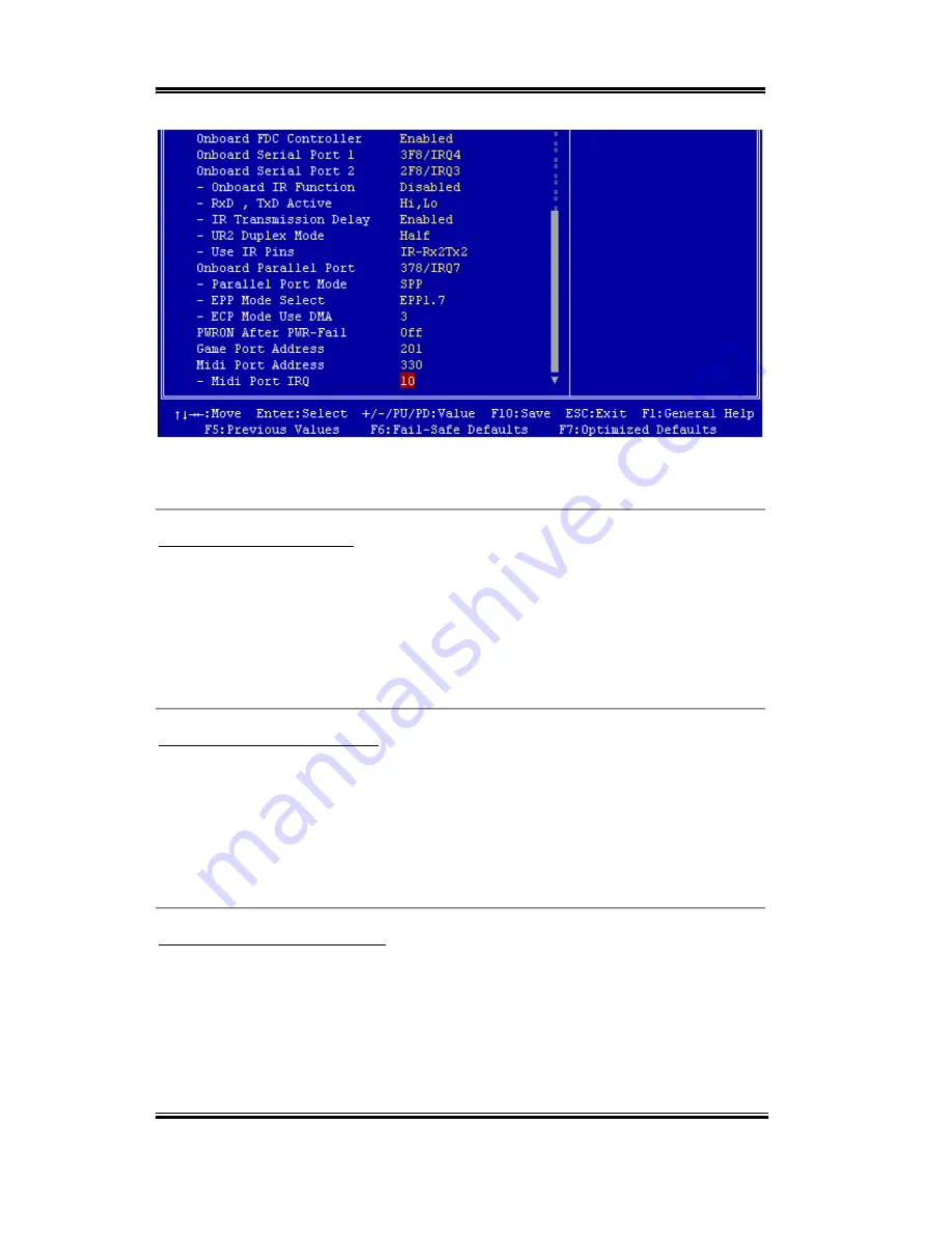
Figure 3-6B. Integrated Peripherals Menu Full Items Screen
Onboard IDE-1 Controller:
The onboard IDE 1 controller can be set as Enabled or Disabled. The default setting is
Enabled
. The integrated peripheral controller contains an IDE interface with support for two
IDE channels. If you choose
Disabled
, it will effect the settings of four items not available.
For example, if you disabled the
Onboard IDE-1 Controller
, you will also disable the
Master/Slave Drive PIO Mode
and
Master/Slave Drive Ultra DMA
.
Master/Slave Drive PIO Mode:
Six options are available: Auto
)
Mode 0
)
Mode 1
)
Mode 2
)
Mode 3
)
Mode 4.
The four IDE PIO (Programmed Input/Output) items let you set a PIO mode (0-4) for each
of the four IDE devices that the onboard IDE interface supports. Modes 0 through 4 provide
successively increased performance. In Auto mode (default setting), the system
automatically determines the best mode for each device.
Master/Slave Drive Ultra DMA:
Two options are available: Auto and Disabled. The default setting is
Auto
. Ultra DMA is a
DMA data transfer protocol that utilizes ATA commands and the ATA bus to allow DMA
commands to transfer data at a maximum burst rate of 33 MB/sec.
Ultra DMA/33 or Ultra DMA/66 implementation is possible only if your IDE hard drive
supports it and the operating environment includes a DMA driver (Windows
®
95 OSR2 or a
Содержание SL6
Страница 2: ......
Страница 8: ...1 4 Chapter1 SL6 1 3 Layout Diagram Figure 1 2 SL6 Motherboard component location ...
Страница 10: ...1 6 Chapter1 SL6 ...
Страница 84: ...A 4 Appendix A SL6 ...
Страница 92: ...C 4 Appendix C SL6 ...
Страница 96: ...D 4 Appendix D SL6 ...
Страница 104: ...Appendix F SL6 F 4 ...
Страница 112: ...Appendix H SL6 H 4 ...
Страница 118: ...Appendix I SL6 I 6 ...
Страница 124: ...Appendix J SL6 J 6 ...
Страница 128: ...Appendix K SL6 K 4 ...
Страница 140: ...N 4 Appendix N SL6 ...
Страница 146: ...O 6 Appendix O SL6 ...


