


Copyright © 2012 - 2017 ABI Electronics Ltd
Page 7
3.4 Quick start guide
This quick guide will help you understand how to use SENTRY and how to run your first scan.
a) Learning a device
From the left hand side menu, click on
Learn
. This section is aimed at acquiring the reference PinPrints of a component. Click
on
New Device
to begin.
Step 1 : Fill in the fields in the
Edit Device
window. The
Component Reference
is normally the part number of the device and
the
Manufacturer
is set for reference purposes. Choose from the drop down menu the
Component Package
. This
represents the number of pins of the device and its shape, and will be displayed in the window. An adapter (if required) will be
automatically selected.
Automatic
settings are recommended for
Reference
and
Scan Profile
(advanced users may refer to
sections VII and VIII for further information). The
Notes
field can be used for any purposes.
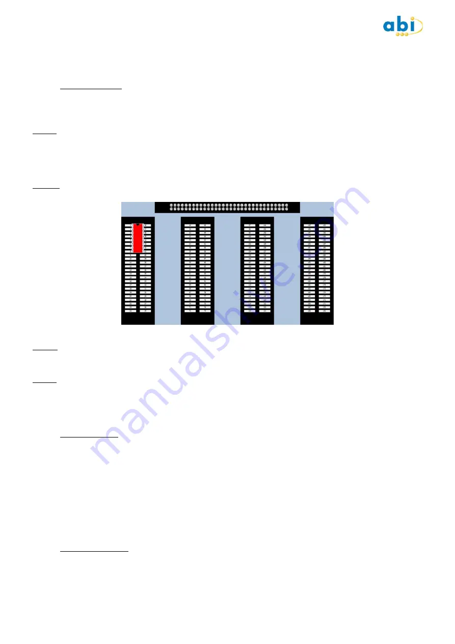
Step 2 : Place the component in the SENTRY unit. By default for DIL packages, this should be on the left ZIF (Zero
Insertion Force) socket, at the top (see picture below).
Step 3 : Click
Learn
. A message will appear asking you to confirm that the IC is in the correct place. Click ok when ready to
initiate the learning process. The unit will apply a complex algorithm to automatically obtain the optimised PinPrints for the
device. Please note that this process is slightly longer than the test and compare process.
Step 4 : Once completed, click
Save
. An indication of date, time and user will be displayed in the
PinPrint
section. Note that the
Clear
button can be used to delete saved PinPrints.
The acquisition of reference PinPrints is now complete. For the purpose of this guide, leave the IC in the socket and move to
the next section by clicking
Test
from the left hand side menu.
b) Testing a device
This section is aimed at testing devices by comparing the PinPrints of a reference component with the PinPrints of the
component under test. The software will automatically select the last device selected in the LEARN section (if applicable). Click
on
Select Device
should you wish to choose a different device.
Click
Test
to begin, with the same device as above still present in the ZIF socket. A blue dot will appear over each pin
successively and a green tick will eventually appear on the device, indicating that the test has passed. Testing is now complete.
Clicking on the
Results
tab will show the PinPrints and their comparison masks. In Matrix reference mode only (see section
8.1), double clicking the PinPrints in the
Results
section will open the PinPrint viewer for advanced viewing.
To test other devices with the same reference, remove the component from the ZIF socket, place another one and click
Test
.
c) Combining PinPrints
This option is used to combine or merge PinPrints together in the same device (this may be useful for devices originating from
different manufacturers). Place another device in the socket after step 4 above and click on
Learn
. Once acquisition is
complete, click on
Save
. A message window will appear, confirming that the PinPrints can be combined or overwritten.


