Copyright © 2012 - 2017 ABI Electronics Ltd
Page 17
a) Adding a new adapter
To add an
Adapter
, click the
New
button to open the
Adapter Editor
with a blank
Adapter
. Carry out the following steps :
Decide on the measurement units for your
Adapter
design. In the
Adapter
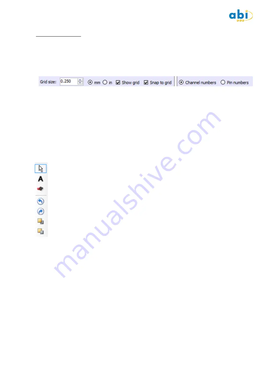
editor, you can use the grid toolbar to
specify the design grid, in inches or millimetres, to use with your
Adapter
. This makes placement of objects easier,
but you can also place objects at arbitrary locations by turning off the
Snap to grid
option. The minimum grid size is
zero (which is equivalent to no grid). You can change the grid by clicking the up down control or by directly typing a
value in the control.
Once you have defined a grid and have
Show grid
and
Snap to grid
enabled, all objects you place and drag will be
positioned on a multiple of the grid setting. When you resize a label, the part of the label you are resizing will be
located on the next available grid boundary. Note however that to resize a label to the grid you should resize both X
and Y dimensions.
Also on the grid toolbar, you can select
Channel numbers
or
Pin numbers
to display on the package(s) included on
your
Adapter
. This allows you to quickly see how the pin numbers on the IC package correspond to the SENTRY
hardware channel numbers. If you click on a pin on a package, you can set the required SENTRY channel number by
entering in the channel property grid at the bottom of the design window.
Select tools form the drawing toolbar. In order to import a predefined package, click on the Add Package tool button
(see below) and select the package from the drop down menu at the bottom of the screen. Then, click on the location
on the grid where you wish to place the package. Use the other functions described below to improve your design :
Selection tool
to allow objects on your
Adapter
to be selected. When you select an object, its properties
(location, colour, font etc) are shown in the property grid at the bottom of the window.
Add label tool
for adding text labels to your
Adapter
. Each label has free text which you can use for
operator guidance when inserting ICs. The label will resize itself automatically depending on the text and
chosen font. You can change the location of the label by dragging with the mouse and/or by using the
controls in the label property grid.
Add package tool
for adding pre-defined packages to your
Adapter
. The location of the package is
displayed in the property grid at the bottom of the window when a package is selected. You can change the
location by dragging with the mouse and/or by using the controls in the property grid. Attached to the
package is a result label, which will be updated with the comparison result at the end of a scan. You can set
the location and size of the result label independently of the package.
Rotate tools
for rotating the selected package or label clockwise or anti-clockwise through 90 degrees.
Bring to front/send to back tools
for setting the Z order of packages and labels when they overlap.
Ensure that
Channel Numbers
is selected in the grid toolbar. Click on each pin in turn and enter the physical
SENTRY channel to be used in the field at the bottom of the screen.
Enter a suitable
Step Prompt
for this scan step – usually instructions on how to place the device correctly for this
step.
Add Scan Steps if required. If the device you wish to test contains more pins than the number of test channels on your
SENTRY, you can test the device in stages. For example, if your device has 256 pins and your SENTRY has 128 pins,
you may still be able to test all the pins on the device by rotating it in its socket and testing again. To allow this, the
Adapter Manager
provides the
Scan Step
feature. For most devices, the scan step is set to 1, but you can add
steps by clicking the scan step up down control in the
Adapter Details
area. Each step can have a different pin to
channel mapping, so that you can use the same SENTRY channels to connect to different pins of your device by
inserting it in a different orientation.
When you scan the device, the
Step Prompt
instructions (free text) will be displayed on the screen to help the
operator. If you do not want this, leave the step prompt blank.
It is important to note that to use an
Adapter
in Manual reference mode with multiple scan steps, a
Device
must
have at least one ground pin available in each scan step.


