


84/100 - 647647/001 - M3371 - 2000/08/30 it-en
9.8.4. Collegamento circuiti ausiliari
Dopo aver eseguito il fissaggio e l’accoppiamento tra i gruppi
di scomparti del quadro, collegare le interconnessioni ausilia-
rie. I fili delle connessioni ausiliarie, muniti di terminale tipo
faston femmina e staccati dalla morsettiera dello scomparto a
cui devono essere accoppiati, sono arrotolati e accostati prov-
visoriamente allo scomparto.
Per consentire una sicura individuazione dei morsetti ai quali
dovranno essere collegati, ciascun filo è normalmente correda-
to da un anellino riportante due numeri. Il primo indica lo
scomparto di destinazione e il secondo il numero del morsetto.
In caso di dubbio fare riferimento allo schema topografico dei
“Collegamenti Interpannellari” sul quale sono rappresentate le
morsettiere dei collegamenti interpannellari, contrassegnate
con la sigla XC, di tutti gli scomparti del quadro. Ogni morsetto
rappresentato riporta l’indicazione per il collegamento dei fili
tra i vari scomparti.
Esempio di collegamento
La sigla “2/1” (morsetto 1-morsettiera XC dello scomparto 3)
indica che il morsetto 1 deve essere collegato alla morsettiera
XC dello scomparto 2 morsetto 1. La sigla “4/1” (morsetto 1-
morsettiera XC dello scomparto 3) indica che il morsetto 1 deve
essere collegato anche alla morsettiera XC dello scomparto 4
morsetto 1.
La posizione delle morsettiere XC è indicativa e deve essere
verificata mediante lo schema topografico dello scomparto.
Per eseguire il collegamento dei circuiti ausiliari fare riferimen-
to allo schema topografico di ogni scomparto.
Ogni scomparto è predisposto con la morsettiera per ricevere
i fili di collegamento provenienti dall’esterno.
Dette morsettiere sono normalmente fornite con morsetti a vite
adatti a ricevere fili di collegamento senza terminali.
Per altre tipologie di collegamento dei circuiti ausiliari attenersi
alle indicazioni fornite con la conferma d’ordine.
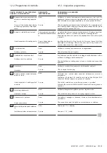
Identificazione delle connessioni interpannellari
1° Gruppo di scomparti
1° Group of cubicles
2° Gruppo di scomparti
2° Group of cubicles
Fig. 80
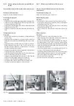
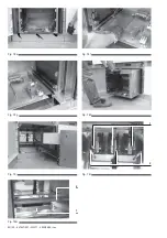
I circuiti secondari dei TV vengono collegati a contatti striscianti
automatici composti da una parte fissa e da una parte mobile
montata sul carrello TV.
I secondari dei TV fuoriescono dalla cella attraverso un foro
posto sul retro della cella.
9.8.4. Auxiliary circuit connection
After fixing and coupling the switchboard cubicle groups, con-
nect the auxiliary interconnections.
The auxiliary connection wires, fitted with female faston termi-
nals and detached from the terminal box of the coupling cubicle,
are rolled up and temporarily put next to the cubicle.
In order to find the right terminals to be connected to them, all
the wires have a small ring with two numbers. The first shows
the relevant cubicle, the second the terminal number.
In case of doubt, refer to the “Panel interconnections” wiring
diagram, which shows the terminal boxes of the inter-panel
connections -marked with code XC- of all the switchboard
cubicles.
Each terminal shown has the indication for connection of the
wires between the various cubicles.
An example of connection
Code “2/1” (terminal 1-terminal box XC of cubicle 3) shows that
terminal 1 must be connected to terminal box XC of cubicle 2
terminal 1.
Code 4/1 (terminal 1-terminal box XC of cubicle 3) shows that
terminal 1 must also be connected to terminal box XC of cubicle
4 terminal 1.
The XC terminal box position is indicative, and must be checked
with the relevant cubicle wiring diagram. For connecting the
auxiliary circuits, refer to the wiring diagram of each cubicle.
Each cubicle has a terminal box for receiving the external
connecting wires.
This type of terminal box is usually equipped with screw termi-
nals for receiving connecting wires without terminals.
For other types of auxiliary circuit connections follow the instruc-
tions contained in the order acknowledgement.
Identification of panel interconnections
The VT auxiliary circuits are connected to automatic sliding
contacts made of a fixed and a moving part mounted on the VT
truck.
The VT auxiliary circuits come out of the compartment passing
through a hole on the rear of the compartment.
Содержание UniSafe PowerIT
Страница 2: ......
Страница 56: ...54 100 647647 001 M3371 2000 08 30 it en 1 Fig 53d Fig 53e ...
Страница 81: ...647647 001 M3371 2000 08 30 it en 79 100 1 2 Fig 75d Fig 75e Fig 75f Fig 75g ...
Страница 84: ...82 100 647647 001 M3371 2000 08 30 it en 1 2 1 2 Fig 78e Fig 78f Fig 78g Fig 78h Fig 78l Fig 78i Fig 78m ...
Страница 103: ......