


647647/001 - M3371 - 2000/08/30 it-en - 27/100
12
11
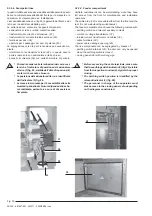
5.3.2.5. Scomparto sbarre principali
Lo scomparto sbarre (fig. 31) contiene il sistema di sbarre
principali del circuito di potenza.
Le sbarre principali sono fissate alle connessioni (11) di deri-
vazione dei contatti fissi superiori del monoblocco (12).
L’isolamento è sempre garantito in aria.
Fig. 31
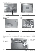
5.3.2.6. Scomparto TV e carrello estraibile
Lo scomparto trasformatori di tensione (fig. 32a) è costituita da
un contenitore nel quale viene inserito un carrello estraibile fig.
32d con a bordo i trasformatori (53) (fig. 32f) e i relativi fusibili
di protezione .
Il carrello estraibile (fig. 32f) è completamente asportabile dallo
scomparto e consente la sostituzione dei fusibili in sicurezza.
Una apposita serranda metallica (57) (fig. 32b) impedisce il
contatto con i terminali di media tensione quando il carrello è
estratto.
Le caratteristiche principali della cella misure sono:
– TV montati su carrello sezionabile all’interno dello scompar-
to;
– il sezionamento dei TV con fusibili incorporati avviene me-
diante maniglia di comando esterna alla cella;
– con il sezionamento dei TV si realizza automaticamente il
sezionamento dei circuiti secondari dei TV;
– con la traslazione del carrello TV si ottiene automaticamente
l’azionamento dell’otturatore metallico;
– i fusibili possono essere sostituiti aprendo la portella, dopo
aver sezionato i TV ed estraendo gli stessi dalla cella;
– la sostituzione dei TV può essere effettuata solo a carrello
estratto dalla cella;
– la segnalazione elettrica di TV inserito ed estratto è fornibile
a richiesta.
Il carrello TV può assumere le seguenti posizioni:
INSERITO:
circuiti principali e secondari TV inseriti;
SEZIONATO:
circuiti principali e secondari TV disinseriti:
il carrello TV rimane in cella;
ESTRATTO:
circuiti principali e secondari TV disinseriti:
carrello TV estratto.
I trasformatori di tensione isolati in resina per l’alimentazione
di misure e protezioni, hanno le prestazioni e le classi di
precisione normalmente previste dai costruttori dei trasforma-
tori di misura.
5.3.2.5. Main busbar compartment
The busbar compartment (fig. 31) contains the power circuit-
main busbar system.
The main busbars are fixed to the branch connectors (11) of the
monobloc upper fixed contacts (12).
Air insulation is always guaranteed.
5.3.2.6. VT compartment and withdrawable truck
The voltage transformer compartment (fig. 32a) consist of an
enclosure where a withdrawable truck is inserted (fig. 32d), with
the transformers on board (53) (fig. 32f) and the relevant
protection fuses.
The withdrawable truck (fig. 32f) can be fully withdrawn from the
compartment and allows safe fuse replacement. A metallic
shutter (57) (fig. 32b) prevents contact with the medium voltage
terminals when the truck is withdrawn.
The main measurement compartment features are:
– VTs mounted on a truck withdrawable inside the compartment
– isolation of the VTs and relevant fuses is by an external
operating handle;
– when the VTs are isolated the VT secondary circuits are also
isolated automatically;
– travel of the VT truck automatically operates the metallic
shutter;
– the fuses can be replaced opening the door, after VT isolation
and withdrawal from the compartment;
– the VTs can be replaced only after withdrawing the truck from
the compartment;
– on request, electrical signalling of VT inserted and withdrawn
positions can be supplied.
The VT truck can take up the following positions:
INSERTED:
VT main and auxiliary circuits connected;
ISOLATED:
VT main and auxiliary circuits disconnected.
The VT truck remains inside the compartment.
WITHDRAWN: VT main and auxiliary circuits disconnected:
VT truck withdrawn.
The voltage transformers insulated in resin for supplying power
to instruments and protection devices, have the performances
and precision classes normally provided by instrument trans-
former manufacturers.
Содержание UniSafe PowerIT
Страница 2: ......
Страница 56: ...54 100 647647 001 M3371 2000 08 30 it en 1 Fig 53d Fig 53e ...
Страница 81: ...647647 001 M3371 2000 08 30 it en 79 100 1 2 Fig 75d Fig 75e Fig 75f Fig 75g ...
Страница 84: ...82 100 647647 001 M3371 2000 08 30 it en 1 2 1 2 Fig 78e Fig 78f Fig 78g Fig 78h Fig 78l Fig 78i Fig 78m ...
Страница 103: ......