


Issue 5 - September 2006
Page 10 of 65
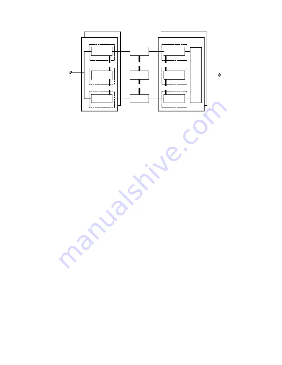
Figure 1 System Overview
2.3.3 Operating
System
The SC300E's Real Time Task Supervisor (RTTS) is a derivative of the CS300 series operating
system that has accrued over 10 million operational hours.
The RTTS is transparent to a user - an SC300E system is programmed like any standard
industrial PLC, and controls the offline/start-up and online/continuous diagnostics.
2.3.4 Off-Line/Start-up
Diagnostics
When an SC300E's processors are first powered up, the following diagnostic routines are
executed: -
•
initialisation of all RAM
•
memory configuration and size checks
•
RTTS and application logic copied to RAM
•
all program checksums recalculated and checked
•
configuration and checksums of neighbouring processors read and
confirmed
•
initialisation of synchronisation registers
•
synchronisation registers of neighbouring processors read and verified
A processor will then pause, waiting for the other two processors to complete their start-up
diagnostics.
At power up an SC300E system must have three healthy processors, otherwise the start-up
diagnostics will prevent execution of the system application logic. The RTTS permits an SC300E
system to operate 3-2-0 i.e. a system will continue to operate with one failed processor. For
ESD safety configurations output modules are configured to de-energise their outputs when the
second processor fails.
Replacement processors can be brought online using a warm start command. Warm start
commands can be issued from a TriBuild workstation or by use of application logic. A newly
installed processor will execute its start-up diagnostics, monitor the running processors’
synchronisation registers and await a warm start command. At this point checksums will be
confirmed and the new processor acquires I/O data tables and the application program from its
neighbours and commences execution of its application logic.
VOTER
2 oo 3
TERMINATION
INPUT
R/O
OUTPUT
TERMINATION
OUTPUT MODULE
INPUT MODULE
R/O
MICRO
CONTROLLER
I/P PATH A
I/P PATH B
CONTROLLER
MICRO
I/P PATH C
CONTROLLER
MICRO
O/P PATH B
CONTROLLER
MICRO
CONTROLLER
O/P PATH A
MICRO
CONTROLLER
MICRO
HOT REPAIR MODULE
HOT REPAIR MODULE
O/P PATH C
A
PROCESSOR
PROCESSOR
C
PROCESSOR
B
R/O
R/O
R/O
R/O
R/O=Read-Only Links


