


Controlled Switching — Buyer´s Guide
H-3
Edition 2, 2006-09
Controlled opening by means of the E3 or
E23 requires an auxiliary contact signal mir-
roring the contact parting instant(s).
Using the E23 for combined controlled clos-
ing and controlled opening excludes the use
of adaptation control for opening. Priority will
automatically be given for adaptation control
on closing.
Controlled opening in adaptive mode when
using the F236 can be arranged individually
for each pole and by supervising the result
of the interruption. This feature can only be
used at reactor de-energizing since a reigni-
tion or restrike at de-energizing capacitive
loads does not necessarily result in a full ad-
ditional current loop.
Adaptive Function of Switchsync
TM
L183 and T183
When using Switchsync™ L83 or T83
controllers there are no fixed energizing
targets; instead they will depend upon the
interrupting conditions reached at the latest
interruption.
Therefore, it is not possible to adapt at fixed
load onset instants. Adaptation control must
be arranged by means of precision auxiliary
contacts supervising the contact touch of the
circuit breaker.
Impact of Substation Configuration
on Adaptation Control Arrangement
The tolerances for the adaptation signal shall
be noted. The substation layout may call for
special solutions in some cases.
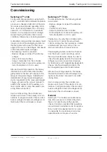
Figure 4 shows an example of a circuit
breaker and a half scheme with controlled
reactor circuit breakers. In this example, all
current transformers are installed outside the
reactor bays.
The current start signal (dashed) when ener-
gizing a reactor may be appropriate, and well
within the current start signal range (0.5 - 5.0
Arms).
However, the problem here is that the reactor
current (dashed) will be low compared to the
rated current flowing between the busbars
(continuous) when they are interconnected.
The CT secondary current flowing through
the controller after energizing the reactor
may be amplified several tenths when the
rated current flows between the busbars. A
high enough current start signal may result
in overcurrent when all circuit breakers are
closed.
This arrangement will require special control
circuits and must be thoroughly checked.
The current transformers shall preferably be
installed in the reactor bays.
Figure 4.
Circuit breaker and a half scheme with CTs outside
reactor bays.
Adaptive Functions
Application
Adaptive Functions
F236
CB1
F236
F236
CB2
CB3


