


Controlled Switching — Buyer´s Guide
G-2
Edition 2, 2006-09
Application
Transmission Lines
Switching of Transmission Lines
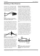
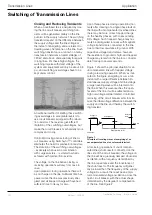
Figure 2.
Example of voltage shape across the open circuit
breaker before reclosing of a shunt compensated line.
Control of Closing and Reclosing
Operations, Uncompensated Lines
For uncompensated lines, controlled switching
of the line circuit breakers may be arranged in
two different ways. Both methods require use
of single-pole operated circuit breakers:
1. Use of Switchsync™ F236
Trapped charge on the line, resulting from the
opening operation, is not recorded.
For closing, a compromise strategy is used
that determines the targets for contact touch
by a certain delay after supply side phase-to-
ground voltage zero. The delayed targeting
is determined by the circuit breaker RDDS
(Rate of Decrease of Dielectric Strength)
with respect to the amplitude of the system
voltage and its frequency. In this manner,
limitation of high overvoltages is achieved ir-
respective of the actual trapped charge. This
is a straightforward method, and the resulting
overvoltage level is often acceptable, espe-
cially when applied in combination with surge
arresters. In many cases, the trapped charge
will actually be zero or close to zero. This will
be the case when sufficient time has elapsed
from the opening operation, or even at re-
closing operations, if the line is equipped with
magnetic voltage transformers. The method
gives best results with circuit breakers having
high RDDS.
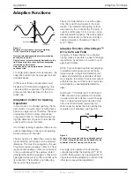
2. Use of Switchsync™ L183
More efficient limitation of switching overvol-
tages is achieved when the trapped charge
on the line is recorded, and taken into con-
sideration by the controlling device. This
solution is especially useful in situations when
considerable trapped charge is to be expect-
ed; i.e. for reclosing operations in situations
when CVTs are used. The initial magnitude
of the trapped charge can be recorded by
the CVTs. As shown in Figure 3, the CVTs
will show the DC voltage level, related to the
trapped charge for a certain time interval
after interruption, and this value will be used
by the controller. Should the time interval
before reclosing exceed 20 s, the controller
will automatically change to the assumption
that the line is uncharged.
Figure 3.
Voltage signals from CVTs during interruption of an unloaded
uncompensated healthy line. The magnetic circuit in the transformer
part goes into saturation after a certain time. The transient response
classes for CVTs may differ but the algorithm used by controller L183
is suitable for determination of the trapped line voltage independent
of CVT class.
R
S
T
Switchsync
F236
C
in
C
out
Load:
Overhead Line
U
ref
Adaptation
R
S
T
Switchsync
L183
O
in
C
in
C
out
U
ref
CVTs
Load:
Overhead Line
C.B.
status
info.
Steady voltage level
after interruption
R
S
T
Vo
lta
ge
ac
ro
ss
CB
For legend, see Page D-4


