


Controlled Switching — Buyer´s Guide
F-6
Edition 2, 2006-09
Application
Power Transformers
Switching of No-load Power Transformers
Control of Closing Operations after
Random Opening Operations
Opening operations are performed at ran-
dom, while the resulting residual flux is de-
termined by integration of the transformer
voltage, see Figure 6. The voltage signals to
the controller for this process may be taken
from normal VTs or CVTs adjacent to the
transformer.
At de-energizing of a transformer by a multi-
unit circuit breaker having voltage grading
capacitors the integral of the load side volt-
ages will not attain a final steady state level
due to the voltages coupled through the ca-
pacitors. Therefore the residual flux is deter-
mined as an average value during a certain
time after interruption.
Based on the calculated residual flux, the
subsequent closing operation is then con-
trolled in such a manner that the inrush cur-
rent is minimized. In this mode of operation,
the residual flux may vary considerably from
one operation to another and the actual con-
trolled making operations will take place at
varying time instants in relation to the supply
(reference) voltage.
The method is mainly suitable for situations
with unplanned operations, under varying
switching conditions and also works when
opening operations occur in connection with
faults in the system. Since each pole needs
to be controlled independently, the method
requires single-pole operation of the circuit
breaker. A suitable controller type is the
Switchsync™ T83.
The adaptive function of the controller must
be used in order to attain sufficient accu-
racy. Signals are obtained from precision
auxiliary contacts on the circuit breaker. The
dielectric properties of the circuit breaker at
closing (RDDS, Rate of Decrease of Dielec-
tric Strength) must be known, and are used
when programming the controller.
The method relies on appropriate signals
from voltage transformers to determine the
residual flux. There are, however, some com-
binations of transformer winding arrange-
ments and positions of voltage transformers
that do not permit determination of the re-
sidual flux. In these cases, the method is not
applicable.
See the separate table on page O-.
Note: When controller type T183 is used for con-
trolled energizing of an unloaded transformer, the
interruptions will not be controlled. However, the
trip signal going directly to the circuit breaker poles
must also be given, in parallel, to the controller. This
trip information is needed to inform the controller
that it should finalize the flux determination.
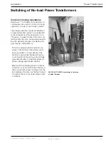
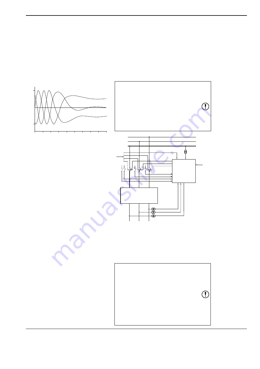
Figure 6.
Residual flux at interruption determined by
integration of transformer voltage. The windings are
D-connected and therefore the three residual fluxes
add up to zero.
0
100 %
-100 %
0
10
20
30
40
50
60
70
80
90
Magnetic flux
Time, ms
Transformers and strategies treated in this
chapter only refer to switching of one trans-
former (three single-phase units or one three-
phase unit). For some applications, parallel
transformers (of different kinds) may be
switched by one circuit breaker. This may be
the case for HVDC converter circuit breakers,
where a transformer group consisting of a
grounded Y - ungrounded
Y transformer is connected in parallel with a
grounded Y / delta connected transformer.
For legend, see Page D-4
R
S
T
Switchsync
T183
O
in
C
in
Load:
No-load Power Transformer
with any level of Remanence
C
out
U
ref