


Controlled Switching — Buyer´s Guide
F-
Edition 2, 2006-09
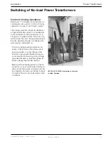
Switching of No-load Power Transformers
Power Transformers
Application
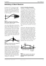
A power transformer in no-load operation, i.e. with
its secondary side unconnected, will consume only
a few amperes of magnetizing current. For reasons
of economy, the core material will be fully utilized,
with magnetic flux reaching up to its knee point, and
the magnetizing current therefore normally having a
pronounced non-sinusoidal shape.
Relation between voltage and flux
The relationship between coil voltage and core flux is:
Therefore, in steady state condition the generated sym-
metrical flux will lead the voltage by 90 electrical degrees.
The symmetrical flux will then in its turn result in a sym-
metrical minimized magnetizing current determined by
the magnetic characteristic of the core.
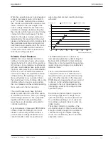
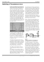
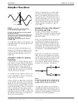
For a single-phase transformer in steady state condition
the relations between voltage, flux and current are graph-
ically illustrated in Figure .
Flux
Flux symmetry
Time
0
0
Time
Flux
Magnetising current
Current
A few Amps
Time
U
I
Voltage
1
2
4
3
1. Steady voltage applied across
the transformer winding
2. Steady flux generated by the
applied voltage
3. Steady symmetrical flux de-
termining the shape of the mag-
netizing characteristics (simpli-
fied in the figure)
4. Resulting steady magnetizing
current determined by the shape
of the magnetizing character-
istics
Power Transformer Design
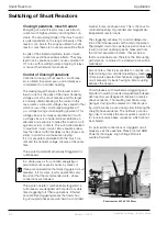
Three-phase power transformers may consist of
three separate single-phase units, or be com-
plete three-phase units with common core and
tank. Common three-phase cores may be of
either five-leg or three-leg design. The primary
and secondary windings may be arranged in
Y-(grounded or ungrounded) or D-configuration.
Tertiary, D-connected windings are sometimes
utilized in cases with Y-connected primary and
secondary windings.
Depending on the core and winding arrange-
ment, the individual phases may or may not in-
fluence each other during switching operations,
and this has to be considered when controlled
switching is applied. The phases will influence
each other in the following cases:
- Ungrounded neutral on the switched side
- Three-leg core
- D-connected secondary or tertiary winding
Figure 1.
Power transformer in steady state no-load condition


