


Controlled Switching — Buyer´s Guide
G-
Edition 2, 2006-09
Transmission Lines
Application
Switching of Transmission Lines
Closing and Reclosing Transients
When an overhead line is energized by clos-
ing the line circuit breaker, switching tran-
sients will be generated mainly on the line,
but also in the supply network. The switching
transients depend on the difference between
the supply voltage and the line voltage at
the instant of energizing, and are related to
traveling wave phenomena on the line. Such
switching transients are a concern on many
transmission networks at rated voltages of
420 kV and above, and especially in regards
to long lines. For these high voltages, the
switching impulse withstand voltage of the
system and equipment will only be about 2-3
p.u. and switching overvoltages have to be
kept under control.
A traditional method of limiting these switch-
ing overvoltages to acceptable levels is to
use circuit breakers equipped with preinser-
tion resistors. The resistors give efficient
limitation of the switching overvoltages, but
make the circuit breakers mechanically more
complex and costly.
Controlled closing and reclosing of line cir-
cuit breakers using Switchsync™ controllers
eliminates the need for preinsertion resistors.
The limitation of the switching overvoltages
– especially when used in combination
with surge arresters – is similar to what is
achieved with preinsertion resistors.
The voltage on the line before closing or
reclosing operations will vary from case to
case.
Upon planned closing operations there will
be no charge on the line. Sufficient time has
passed since the line was previously ener-
gized and all trapped charge will have had
sufficient time to decay for zero.
Upon three-phase reclosing operations (nor-
mally after clearing of a single-phase fault on
the line) with uncompensated overhead lines,
there may be more or less trapped charge
on the healthy phases, with corresponding
DC voltage. Such trapped charge may nor-
mally be disregarded in cases with magnetic
voltage transformers connected to the line,
due to their low resistance to ground. With
capacitive voltage transformers, however,
the resistance to ground is high, and trapped
charge may remain on the line for a consider-
able time up to several seconds.
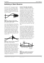
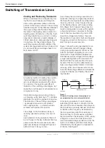
Figure shows the principal situation for an
uncompensated line with trapped voltage
during a reclosing operation. When, as indi-
cated in the figure, energizing occurs at an
instant with a large difference between (in-
stantaneous) supply voltage and line voltage,
a large traveling wave will be injected onto
the line. When this wave reaches the open,
far end of the line, it will be reflected and a
high overvoltage will be initiated. Controlled
reclosing of the circuit breaker aims to mini-
mize the initial voltage difference between the
supply and the line, and thereby the switch-
ing transient.
Figure 1.
Principle of traveling waves at energizing of an
uncompensated line at an unfavorable instant.
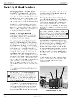
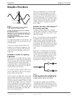
At reclosing operations of shunt compen-
sated lines (shunt reactor connected on the
line side of the circuit breaker), the voltage on
the line will be a gradually damped sinusoidal
oscillation, with a frequency determined by
the line capacitance and the inductance of
the shunt reactor. The frequency will gener-
ally be lower than the frequency of the supply
voltage. As a result, there will be an ampli-
tude modulated voltage oscillation across the
open circuit breaker, with the actual shape
determined by the degree of compensation
of the line. See Figure 2.
Trapped voltage on line
Substation
Open end
Line
Voltage in
substation
Traveling wave
Reflected
wave


