
ABB | SACE Emax 2
Putting into service and maintenance
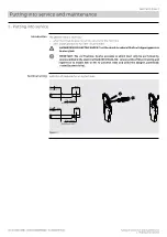
1 - Putting into service
47 | © 2023 ABB | 1SDH001000R0002 - ECN000297030
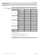
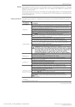
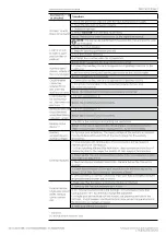
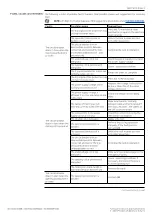
Accessories
(*)
to
be checked
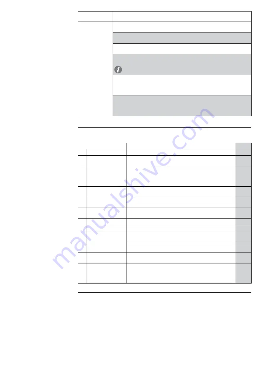
Procedure
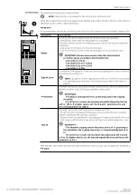
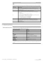
Zone selectivity
1. Check selectivity connections (between Ekip Touch and the other units) as
shown in circuit diagrams
2. Provide Ekip Touch with auxiliary power and make sure that CB status is:
Open
3. Check that the protection of the selectivity concerned has been enabled
(example: S protection)
4. Select the
Test - Zone Selectivity menu and the submenu of the protection
concerned; repeat points 5, 6, 7 and 8 for each protection activated
NOTE
:
for selectivity D, consider submenu S for the Forward connections
and G for the Backward connections
Check
Output
:
5. Select the
Force Output command and check, on the unit connected to the
Ekip Touch output, that the state of its
Input =
ON
6. Select
Release Output and check on the unit that Input =
OFF
Check
Input
:
7. Select the
Force Output command in the unit connected to the Ekip Touch
input; check on Trip unit:
Input =
ON
8. Select
Release Output and check on Trip unit: Input =
OFF
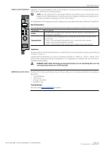
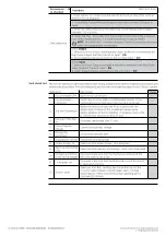
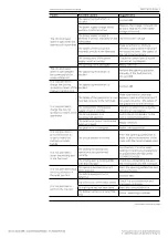
Final check list
Perform the operations described below after having completed the general inspection procedures and
checked the accessories. Print this sheet and use it to make an inspection report in the "Checks" column.
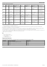
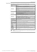
Operation
Description
Check
1
Circuit-breaker OFF
Open the circuit-breaker
2
Circuit-breaker
connected
Switch the circuit-breaker in withdrawable version to the
connected position and reposition the crank in its seat
3
Trip unit Parameters
Adjust the protection trip unit in accordance with the
design specifications of the installation (drawn up by
design engineer of the installation). If necessary, power the
protection trip unit with an Ekip TT unit
4
Removal of the Ekip
TT
If present, remove the Ekip TT unit
5
Connecting the
voltage
Connect the auxiliary voltage
6
Closing the
switchgear
Close the switchgear door
7
Charging the springs Charge the closing springs
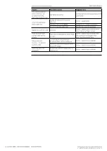
8
Undervoltage coil
Make sure that undervoltage coil is energized
9
Opening and closing
coils
Make sure that opening and closing coils are NOT energized
10
Mechanical interlock
of the circuit-breaker
If present, make sure that the mechanical interlock of the
circuit-breaker is not active
11
Locking devices
If present, make sure that the locking devices of the circuit-
breaker are not active
12
Status signals
Make sure that the signalling devices on the front of the
circuit-breaker indicate: circuit-breaker open - springs
discharged O - OPEN and white spring signalling device
DISCHARGED SPRING


