
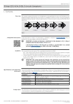

ABB | SACE Emax 2
Management operations
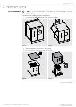
2 - Unpacking and handling
11 | © 2023 ABB | 1SDH001000R0002 - ECN000297030
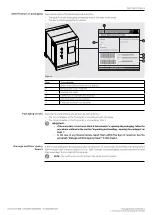
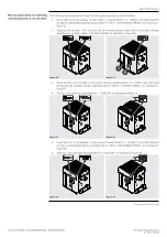
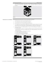
Continued from the previous page
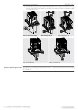
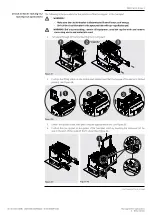
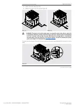
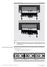
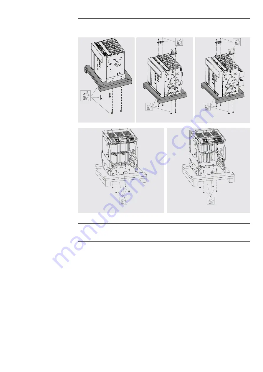
4. Take out the screws (See Figure 10 Fixed circuit-breaker). Take out the screws and the mounting
brackets (See Figure 11 Moving part IEC, Figure 12 Moving part UL, Figure 13 Fixed part IEC and
Figure 14 Fixed part UL).
Figure 10 Fixed circuit-breaker
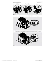
Figure 11 Moving part IEC
Figure 12 Moving part UL
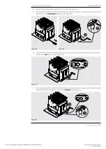
Figure 13 Fixed part IEC
Figure 14 Fixed part UL
Disposal of packing materials
For disposal of the packaging materials see the chapter " 4 - Decommissioning and treatment at end of
life " on page 52.


