8.3
Configuration models (2)
GUID-FF31106B-B069-4A67-A0A4-DA6D0298D52A v3
FUNCT.
I/O
Objects
A B
B
ES
C
RE
B
50
0
Read
y
Star
t
Tri
p
Clea
r
Hel
p
Men
u
L
R
ABB
3
2
1
I
A B
B
ES
C
RE
B
50
0
Read
y
Star
t
Tri
p
Clea
r
Hel
p
Men
u
L
R
ABB
3
2
1
I
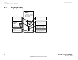
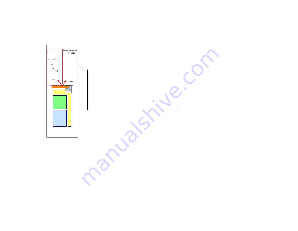
Bay Unit
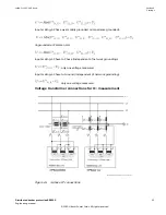
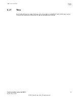
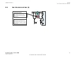
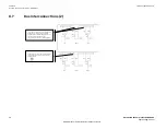
Bay Model containing more than one Bay Figure
A Bay Model can contain more than one Bay Figure (for example, a feeder bay +
bus section disconnectors), while only one Bay Unit Model (one Bay Unit) is used.
This under the condition, that the following limitations are not exceeded.
Maximum per bay unit:
•
1 CB object
•
1 CT object (represents 4I-inputs
→
for example, I
3ph
+ I
ground
)
•
1 VT object (represents 5U-inputs
→
for example, U
3ph
+ U
BB1
+ U
BB2
)
From the Bay Model side, the number of disconnectors is not limited, if the
number of binary inputs is sufficient.
ANSI18000617 V1 EN-US
Section 8
1MRK 511 452-UUS Rev. A
Annex A | Configurator mode - Definitions
46
Distributed busbar protection REB500
Engineering manual
© 2020 Hitachi Power Grids. All rights reserved


