


9.25
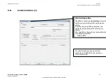
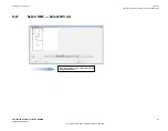
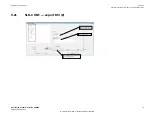
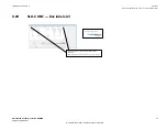
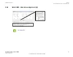
SLD-CONF — completion of single-line diagram
GUID-7D58F271-2EB4-4A9E-A9AD-4C91611AEEE5 v3
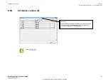
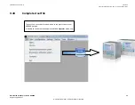
Now, the single-line diagram shall be completed
step by step by importing the typical Bay Models
from the User Bay Model database.
Import buttons to be used.
ANSI18000851 V1 EN-US
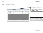
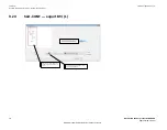
9.26
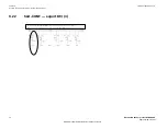
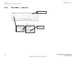
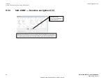
SLD-CONF — Positioning of bay figures
GUID-3FE8F16D-6293-4CB6-8FBD-97BF8CBFB112 v3
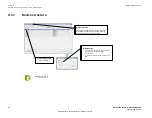
In case of
Multiple Bay Models
, change over to
Figure
mode, select the relevant Bay Figure (for
example, bus section disconnector figure) and
move it to the appropriate position of the
single-line diagram.
Figure
mode
Moved Bay Model
Bay Figure to be moved.
Multiple Bay Model
Move
buttons
ANSI18000852 V1 EN-US
1MRK 511 452-UUS Rev. A
Section 9
Annex B | Configurator mode - System configuration
Distributed busbar protection REB500
75
Engineering manual
© 2020 Hitachi Power Grids. All rights reserved