6.8
Circuit breakers
GUID-1D7E9DA9-CFDF-4453-8945-6B8CE3868C41 v1
For detailed information about setting and configuration, see
REB500 Technical Manual, section
Circuit breakers.
6.9
Disconnectors
GUID-2FE5781F-5572-44E0-A613-AFFB193F4F79 v2
For detailed information about setting and configuration, see
REB500 Technical Manual, section
Disconnectors.
6.10
Current transformers
GUID-F024399D-3EA5-466F-8970-8E3237F8299A v1
For detailed information about setting and configuration, see
REB500 Technical Manual, section
Current transformers.
6.11
Voltage transformers
GUID-30DABA81-43A8-4222-A46B-E9F26D72D257 v1
For detailed information about setting and configuration, see
REB500 Technical Manual, section
Voltage transformers.
6.12
Voltage/ external release
GUID-5658FD39-6699-4B3F-AB1F-9B14053746F1 v2
For detailed information about setting and configuration, see
REB500 Technical Manual, section
Voltage/ external release.
Supplementary information necessary for configuration
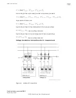
The under voltage release criteria is performed with the normalized voltage amplitudes. The
voltage limit UL is in relation to the defined nominal voltage UN of the corresponding voltage
transformer.
Abbreviations
•
U
L
Voltage limit
•
U
N
Nominal voltage (phase-phase)
The scaling of 1/√3 in case of phase to ground configuration (3-phase wye, 1-phase to ground) is
done internally by the algorithm.
For more information about settings and calculations, refer to the document
Ground fault
protection for high voltage busbars, 1KHL 020319-Aen.
The number of activated measurements depends on the setting of the Bay Unit input voltage
scaling and on the setting of the network grounding:
Input scaling: 3-Phase Delta (independent of network grounding):
Section 6
1MRK 511 452-UUS Rev. A
Settings
32
Distributed busbar protection REB500
Engineering manual
© 2020 Hitachi Power Grids. All rights reserved

