background image

14.  Human machine interface

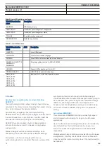
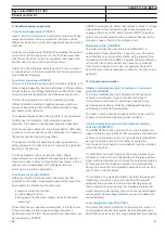
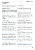
Local HMI

AMU0600442 v14

IEC13000239-2-en.vsd

IEC13000239 V2 EN-US

Figure 5.

Local human-machine interface

The LHMI of the IED contains the following elements:
• Graphical display capable of showing a user defined single

line diagram and provide an interface for controlling
switchgear.

• Navigation buttons and five user defined command buttons

to shortcuts in the HMI tree or simple commands.

• 15 user defined three-color LEDs.
• Communication port for PCM600.

The LHMI is used for setting, monitoring and controlling.

15.  Basic IED functions

Time synchronization

M11344-3 v9

The time synchronization function is used to select a common
source of absolute time for the synchronization of the IED
when it is a part of a control and a protection system. This
makes it possible to compare events and disturbance data
between all IEDs within a station automation system and in
between sub-stations. A common source shall be used for
IED and merging unit when IEC 61850-9-2LE process bus
communication is used.

16.  Station communication

Communication protocols

M14815-3 v12

Each IED is provided with a communication interface,
enabling it to connect to one or many substation level
systems or equipment, either on the Substation Automation
(SA) bus or Substation Monitoring (SM) bus.

Available communication protocols are:

• IEC 61850-8-1 communication protocol
• IEC 61850-9-2LE communication protocol
• LON communication protocol
• SPA or IEC 60870-5-103 communication protocol
• DNP3.0 communication protocol

Several protocols can be combined in the same IED.

IEC 61850-8-1 communication protocol

M14787-3 v12

IEC 61850 Ed.1 or Ed.2 can be chosen by a setting in
PCM600. The IED is equipped with single or double optical
Ethernet rear ports (order dependent) for IEC 61850-8-1
station bus communication. The IEC 61850-8-1
communication is also possible from the electrical Ethernet
front port. IEC 61850-8-1 protocol allows intelligent electrical
devices (IEDs) from different vendors to exchange information
and simplifies system engineering. IED-to-IED communication
using GOOSE and client-server communication over MMS are
supported. Disturbance recording file (COMTRADE) uploading
can be done over MMS or FTP.

IEC 61850-9-2LE communication protocol

GUID-C3AA21B4-730F-4327-943A-3C77102A80A0 v2

Single optical Ethernet port communication standard IEC
61850-9-2LE for process bus is provided. IEC 61850-9-2LE
allows Non Conventional Instrument Transformers (NCIT) with
Merging Units (MU) or stand alone Meging Units to exchange
information with the IED and simplifies SA engineering.

LON communication protocol

SEMOD120140-5 v2

Existing stations with ABB station bus LON can be extended
with use of the optical LON interface. This allows full SA
functionality including peer-to-peer messaging and
cooperation between the IEDs.

SPA communication protocol

SEMOD120134-5 v1

A single glass or plastic port is provided for the ABB SPA
protocol. This allows extensions of simple substation
automation systems but the main use is for Substation
Monitoring Systems SMS.

IEC 60870-5-103 communication protocol

SEMOD120137-5 v3

A single glass or plastic port is provided for the IEC
60870-5-103 standard. This allows design of simple
substation automation systems including equipment from
different vendors. Disturbance files uploading is provided.

DNP3.0 communication protocol

SEMOD153688-5 v1

An electrical RS485 and an optical Ethernet port is available
for the DNP3.0 communication. DNP3.0 Level 2

1MRK 511 361-BEN B

Bay control REC670 2.1 IEC


Product version: 2.1


ABB

31

Содержание REC670 2.1 IEC

Страница 1: ...Relion 670 series Bay control REC670 2 1 IEC Product guide ...

Страница 2: ...cal data 36 21 Ordering for customized IED 96 22 Ordering for pre configured IED 106 23 Ordering for Accessories 111 Disclaimer The information in this document is subject to change without notice and should not be construed as a commitment by ABB ABB assumes no responsibility for any errors that may appear in this document Drawings and diagrams are not binding Copyright 2016 ABB All rights reserv...

Страница 3: ...e a breaker failure function independent from the protection IEDs also for a complete one and a half breaker diameter Disturbance recording and fault locator are available to allow independent post fault analysis after primary disturbances in case of a failure in the protection system Duplex communication channels for transfer of up to 192 intertrip and binary signals are available on each remote ...

Страница 4: ..._67 4 3I EF PIOC 50N IN EF4 PTOC 51N_67N 4 IN LF PTTR 26 θ SDE PSDE 67N IN UV2 PTUV 27 2 3U SA PTOF 81 f OV2 PTOV 59 2 3U GOP PDOP 32 P SA PFRC 81 df dt GUP PDUP 37 P TR PTTR 49 θ CV GAPC 2 I U ZCRW PSCH 85 LMB RFLO 21FL FL EC PSCH 85 ZC PSCH 85 TR8 ATCC 90 U ECRW PSCH 85 TR1 ATCC 90 U ZCLC PSCH ROV2 PTOV 59N 2 U0 SA PTUF 81 f VD SPVC 60 Ud S SIMG 63 S SIML 71 SMP PTRC 94 1 0 CC RBRF 50BF 3I BF VN...

Страница 5: ...V 59 2 3U GOP PDOP 32 P SA PFRC 81 df dt GUP PDUP 37 P TR PTTR 49 CV GAPC 2 I U ZCRW PSCH 85 LMB RFLO 21FL FL EC PSCH 85 ZC PSCH 85 TR8 ATCC 90 U ECRW PSCH 85 TR1 ATCC 90 U ZCLC PSCH ROV2 PTOV 59N 2 U0 SA PTUF 81 f FUF SPVC U I S SIMG 63 S SIML 71 SMP PTRC 94 1 0 CC RBRF 50BF 3I BF VN MMXU MET UN C MSQI MET Isqi S CILO 3 Control S CSWI 3 Control S XCBR 3 Control VN MMXU MET UN SMB RREC 79 5 0 1 WA...

Страница 6: ... QC9 3 Control VD SPVC 60 Ud S SIMG 63 S SIML 71 CC RBRF 50BF 3I BF TR PTTR 49 θ SMB RREC 79 5 0 1 SMP PTRC 94 1 0 LF PTTR 26 θ LC PTTR 26 θ C MMXU MET I C MSQI MET Isqi FUF SPVC U I WA1 WA2_VT WA1_VT WA2 LINE_VT LINE_CT1 LINE_CT2 S CILO 3 Control S CSWI 3 Control S XSWI 3 Control S CILO 3 Control S CSWI 3 Control S XSWI 3 Control VN MMXU MET UN S CILO 3 Control S CSWI 3 Control S XCBR 3 Control V...

Страница 7: ...V 27 3U VDC PTOV 60 Ud CCS SPVC 87 INd I TCL YLTC 84 NS4 PTOC 46I2 4 I2 LC PTTR 26 Optional Functions HZ PDIF 87 Id PH PIOC 50 3I OC4 PTOC 51_67 4 3I EF PIOC 50N IN EF4 PTOC 51N_67N 4 IN LF PTTR 26 SDE PSDE 67N IN UV2 PTUV 27 2 3U SA PTOF 81 f OV2 PTOV 59 2 3U GOP PDOP 32 P SA PFRC 81 df dt GUP PDUP 37 P ZCRW PSCH 85 LMB RFLO 21FL FL EC PSCH 85 ZC PSCH 85 TR8 ATCC 90 U ECRW PSCH 85 TR1 ATCC 90 U Z...

Страница 8: ...tities 3 A03 optional function included in packages A03 refer to ordering details IEC 61850 ANSI Function description Bay control REC670 Customized REC670 A30 REC670 A31 REC670 B30 REC670 C30 Differential protection HZPDIF 87 1Ph high impedance differential protection 0 6 3 A02 3 A02 3 A02 6 A07 1MRK 511 361 BEN B Bay control REC670 2 1 IEC Product version 2 1 8 ABB ...

Страница 9: ...0 6 1 C51 1 C51 1 C52 1 C53 TRPTTR 49 Thermal overload protection two time constant 0 6 1 C51 1 C51 1 C52 1 C53 CCRBRF 50BF Breaker failure protection 0 6 1 C51 1 C51 1 C52 1 C53 STBPTOC 50STB Stub protection 0 3 CCPDSC 52PD Pole discordance protection 0 6 1 1 2 3 GUPPDUP 37 Directional underpower protection 0 2 1 C17 1 C17 1 C17 1 C17 GOPPDOP 32 Directional overpower protection 0 2 1 C17 1 C17 1 ...

Страница 10: ...on 0 6 6 E01 6 E01 6 E01 6 E01 FTAQFVR 81A Frequency time accumulation protection 0 12 Multipurpose protection CVGAPC General current and voltage protection 0 9 4 F01 4 F01 4 F01 4 F01 General calculation SMAIHPAC Multipurpose filter 0 6 1 67 requires voltage 2 67N requires voltage 1MRK 511 361 BEN B Bay control REC670 2 1 IEC Product version 2 1 10 ABB ...

Страница 11: ...4 1 H15 1 H15 1 H15 2 H18 TCMYLTC 84 Tap changer control and supervision 6 binary inputs 0 4 4 4 4 4 TCLYLTC 84 Tap changer control and supervision 32 binary inputs 0 4 4 4 4 4 SLGAPC Logic rotating switch for function selection and LHMI presentation 15 15 15 15 15 VSGAPC Selector mini switch 20 20 20 20 20 DPGAPC Generic communication function for Double Point indication 16 16 16 16 16 SPC8GAPC S...

Страница 12: ...VERTERQT ORQT PULSETIMERQT RSMEMORYQT SRMEMORYQT TIMERSETQT XORQT Configurable logic blocks Q T see Table 3 0 1 AND GATE INV LLD OR PULSETIMER SLGAPC SRMEMORY TIMERSET VSGAPC XOR Extension logic package see Table 4 0 1 FXDSIGN Fixed signal function block 1 1 1 1 1 B16I Boolean 16 to Integer conversion 18 18 18 18 18 BTIGAPC Boolean 16 to Integer conversion with Logic Node representation 16 16 16 1...

Страница 13: ... 21 21 SSIML 71 Liquid medium supervision 3 3 3 3 3 SSCBR Circuit breaker monitoring 0 18 3 M13 3 M13 6 M15 9 M17 LMBRFLO Fault locator 0 1 1 M01 1 M01 1 M01 1 M01 I103MEAS Measurands for IEC 60870 5 103 1 1 1 1 1 I103MEASUSR Measurands user defined signals for IEC 60870 5 103 3 3 3 3 3 I103AR Function status auto recloser for IEC 60870 5 103 1 1 1 1 1 I103EF Function status earth fault for IEC 60...

Страница 14: ...figurable logic blocks Q T Total number of instances ANDQT 120 INDCOMBSPQT 20 INDEXTSPQT 20 INVALIDQT 22 INVERTERQT 120 ORQT 120 PULSETIMERQT 40 RSMEMORYQT 40 SRMEMORYQT 40 TIMERSETQT 40 XORQT 40 Table 4 Total number of instances for extended logic package Extended configurable logic block Total number of instances AND 180 GATE 49 INV 180 LLD 49 OR 180 PULSETIMER 59 SLGAPC 74 SRMEMORY 110 TIMERSET...

Страница 15: ...tion protocol 1 1 1 1 1 MST1TCP MST2TCP MST3TCP MST4TCP DNP3 0 for serial communication protocol 1 1 1 1 1 DNPFREC DNP3 0 fault records for TCP IP and EIA 485 communication protocol 1 1 1 1 1 IEC 61850 8 1 Parameter setting function for IEC 61850 1 1 1 1 1 GOOSEINTLKRCV Horizontal communication via GOOSE for interlocking 59 59 59 59 59 GOOSEBINRCV GOOSE binary receive 16 16 16 16 16 GOOSEDPRCV GOO...

Страница 16: ...1 1 1 1 SINGLELCCH Single ethernet port link status 1 1 1 1 1 PRPSTATUS Dual ethernet port link status 1 1 1 1 1 Process bus communication IEC 61850 9 2 1 PRP IEC 62439 3 parallel redundancy protocol 0 1 1 P03 1 P03 1 P03 1 P03 Remote communication Binary signal transfer receive transmit 6 36 6 36 6 36 6 36 6 36 Transmission of analog data from LDCM 1 1 1 1 1 Receive binary status from remote LDCM...

Страница 17: ...ignal matrix for binary outputs SMMI Signal matrix for mA inputs SMAI1 SMAI12 Signal matrix for analog inputs 3PHSUM Summation block 3 phase ATHSTAT Authority status ATHCHCK Authority check AUTHMAN Authority management FTPACCS FTP access with password SPACOMMMAP SPA communication mapping SPATD Date and time via SPA protocol DOSFRNT Denial of service frame rate control for front port DOSLANAB Denia...

Страница 18: ...d to ensure that closing can be done safely SESRSYN function includes a built in voltage selection scheme for double bus and 1 breaker or ring busbar arrangements Manual closing as well as automatic reclosing can be checked by the function and can have different settings For systems which are running asynchronous a synchronizing function is provided The main purpose of the synchronizing function i...

Страница 19: ... Operation counter The apparatus control function is realized by means of a number of function blocks designated Bay control QCBAY Switch controller SCSWI Circuit breaker SXCBR Circuit switch SXSWI The three latter functions are logical nodes according to IEC 61850 8 1 To realize the reservation function also the function blocks Reservation input RESIN and Bay reserve QCRSV are included in the app...

Страница 20: ...e methods are available the master follower method the circulating current method and the reverse reactance method The first two methods require exchange of information between the parallel transformers and this is provided for within IEC 61850 8 1 Voltage control includes many extra features such as possibility of to avoid simultaneous tapping of parallel transformers hot stand by regulation of a...

Страница 21: ...e polarized with memory The function can be set to be directional or non directional independently for each of the steps A second harmonic blocking level can be set for the function and can be used to block each step individually Instantaneous residual overcurrent protection EFPIOC M12701 3 v14 The Instantaneous residual overcurrent protection EFPIOC has a low transient overreach and short trippin...

Страница 22: ...ill experience forced ageing As a consequence of this the risk of internal phase to phase or phase to earth faults will increase The thermal overload protection estimates the internal heat content of the transformer temperature continuously This estimation is made by using a thermal model of the transformer with two time constants which is based on current measurement Two warning levels are availa...

Страница 23: ...undervoltage protection UV2PTUV M13789 3 v11 Undervoltages can occur in the power system during faults or abnormal conditions Two step undervoltage protection UV2PTUV function can be used to open circuit breakers to prepare for system restoration at power outages or as long time delayed back up to primary protection UV2PTUV has two voltage steps each with inverse or definite time delay UV2PTUV has...

Страница 24: ...13023B93B4D1 v4 Frequency time accumulation protection FTAQFVR is based on measured system frequency and time counters FTAQFVR for generator protection provides the START output for a particular settable frequency limit when the system frequency falls in that settable frequency band limit and positive sequence voltage within settable voltage band limit The START signal triggers the individual even...

Страница 25: ... is designed to detect fuse failures or faults in voltage measurement circuit based on phase wise comparison of voltages of main and pilot fused circuits VDSPVC blocking output can be configured to block functions that need to be blocked in case of faults in the voltage circuit Multipurpose filter SMAIHPAC GUID EB0B11C3 FF79 4B8D A335 649623E832F9 v2 The multi purpose filter function block SMAIHPA...

Страница 26: ...detection requires a sufficient minimum residual fault current out from this IED The fault current can be too low due to an opened breaker or high positive and or zero sequence source impedance behind this IED To overcome these conditions weak end infeed WEI echo logic is used The weak end infeed echo is limited to 200 ms to avoid channel lockup 11 Logic Tripping logic SMPPTRC M12275 3 v10 A funct...

Страница 27: ...n the local HMI Fixed signal function block M15322 3 v11 The Fixed signals function FXDSIGN generates nine pre set fixed signals that can be used in the configuration of an IED either for forcing the unused inputs in other function blocks to a certain level value or for creating certain logic Boolean integer floating point string types of signals are available One FXDSIGN function block is include...

Страница 28: ... analog and 352 binary signals The Disturbance report functionality is a common name for several functions Event list Indications Event recorder Trip value recorder Disturbance recorder Fault locator The Disturbance report function is characterized by great flexibility regarding configuration starting conditions recording times and large storage capacity A disturbance is defined as an activation o...

Страница 29: ...munication Analog and double indication values are also transferred through EVENT function Generic communication function for Single Point indication SPGAPC SEMOD55713 5 v7 Generic communication function for Single Point indication SPGAPC is used to send one single logical signal to other systems or equipment in the substation Generic communication function for Measured Value MVGAPC SEMOD55872 5 v...

Страница 30: ...t Possibility for manual addition of accumulated time Reporting of the accumulated time 13 Metering Pulse counter logic PCFCNT M13394 3 v7 Pulse counter logic PCFCNT function counts externally generated binary pulses for instance pulses coming from an external energy meter for calculation of energy consumption values The pulses are captured by the binary input module and then read by the PCFCNT fu...

Страница 31: ...D is equipped with single or double optical Ethernet rear ports order dependent for IEC 61850 8 1 station bus communication The IEC 61850 8 1 communication is also possible from the electrical Ethernet front port IEC 61850 8 1 protocol allows intelligent electrical devices IEDs from different vendors to exchange information and simplifies system engineering IED to IED communication using GOOSE and...

Страница 32: ...ivered with 19 rack mounting accessories 18 Hardware description Hardware modules IP14529 1 v1 Power supply module PSM M11595 3 v5 The power supply module is used to provide the correct internal voltages and full isolation between the IED and the battery system An internal fail alarm output is available Binary input module BIM M1769 3 v4 The binary input module has 16 optically isolated inputs and...

Страница 33: ...n with a dedicated Master and the rest are slaves No special control signal is needed in this case GPS time synchronization module GTM M14851 3 v4 This module includes a GPS receiver used for time synchronization The GPS has one SMA contact for connection to an antenna It also includes an optical PPS ST connector output IRIG B Time synchronizing module SEMOD141113 4 v7 The IRIG B time synchronizin...

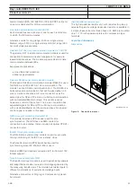
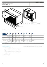
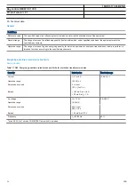
Страница 34: ...2 190 5 7 50 316 0 12 4 228 6 9 00 6U 1 1 x 19 265 9 10 47 448 3 17 65 242 1 9 53 255 8 10 07 430 3 16 86 190 5 7 50 428 3 16 86 465 1 18 31 228 6 9 00 482 6 19 00 The H and K dimensions are defined by the 19 rack mounting kit Mounting alternatives M16079 3 v12 19 rack mounting kit Flush mounting kit with cut out dimensions 1 2 case size h 254 3 mm 10 01 w 210 1 mm 8 27 3 4 case size h 254 3 mm 10...

Страница 35: ...ation Connection diagrams for Customized products Connection diagram 670 series 2 11MRK002801 AF Connection diagrams for Configured products Connection diagram REC670 2 1 A30 1MRK002803 FA Connection diagram REC670 2 1 A31 1MRK002803 FD Connection diagram REC670 2 1 B30 1MRK002803 FB Connection diagram REC670 2 1 C30 1MRK002803 FC Connection diagrams for Customized products Connection diagram 670 ...

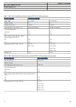
Страница 36: ...unctions according to the specified requirements Energizing quantities rated values and limits IP15765 1 v2 Analog inputs IP15842 1 v1 M16988 1 v9 Table 7 TRM Energizing quantities rated values and limits for protection transformer modules Quantity Rated value Nominal range Current Ir 1 or 5 A 0 2 40 Ir Operative range 0 100 x Ir Permissive overload 4 Ir cont 100 Ir for 1 s Burden 150 mVA at Ir 5 ...

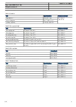
Страница 37: ...ge 5 10 20mA 0 5 0 10 0 20 4 20mA Power consumption each mA board each mA input 2 W 0 1 W SEMOD55310 2 v8 Table 10 OEM Optical ethernet module Quantity Rated value Number of channels 1 or 2 port A B for IEC 61850 8 1 IEEE C37 118 and port C D for IEC 61850 9 2LE IEEE C37 118 Standard IEEE 802 3u 100BASE FX Type of fiber 62 5 125 mm multimode fibre Wave length 1300 nm Optical connector Type ST Comm...

Страница 38: ... 1 20ms Maximum 176 binary input channels may be activated simultaneously with influencing factors within nominal range M50609 2 v6 Table 13 BIM Binary input module with enhanced pulse counting capabilities Quantity Rated value Nominal range Binary inputs 16 DC voltage RL 24 30 V 48 60 V 110 125 V 220 250 V RL 20 RL 20 RL 20 RL 20 Power consumption 24 30 V 48 60 V 110 125 V 220 250 V max 0 05 W in...

Страница 39: ...10 125 V 220 250 V RL 20 RL 20 RL 20 RL 20 Power consumption 24 30 V 50 mA 48 60 V 50 mA 110 125 V 50 mA 220 250 V 50 mA 220 250 V 110 mA max 0 05 W input max 0 1 W input max 0 2 W input max 0 4 W input max 0 5 W input Counter input frequency 10 pulses s max Oscillating signal discriminator Blocking settable 1 40 Hz Release settable 1 30 Hz Debounce filter Settable 1 20 ms 1MRK 511 361 BEN B Bay c...

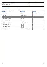
Страница 40: ...ts 10 2 Max system voltage 250 V AC DC 250 V DC Test voltage across open contact 1 min 1000 V rms 800 V DC Current carrying capacity Per relay continuous Per relay 1 s Per process connector pin continuous 8 A 10 A 12 A 8 A 10 A 12 A Making capacity at inductive load with L R 10 ms 0 2 s 1 0 s 30 A 10 A 0 4 A 0 4 A Making capacity at resistive load 0 2 s 1 0 s 30 A 10 A 220 250 V 0 4 A 110 125 V 0 ...

Страница 41: ...ignal relays parallel reed relay Binary outputs IOM 10 IOM 2 Max system voltage 250 V AC DC 250 V DC Test voltage across open contact 1 min 250 V rms 250 V rms Current carrying capacity Per relay continuous Per relay 1 s Per process connector pin continuous 8 A 10 A 12 A 8 A 10 A 12 A Making capacity at inductive loadwith L R 10 ms 0 2 s 1 0 s 30 A 10 A 0 4 A 0 4 A Making capacity at resistive loa...

Страница 42: ...s 10A 10A Breaking capacity for DC with L R 40ms 48V 1A 110V 0 4A 60V 0 75A 125V 0 35A 220V 0 2A 250V 0 15A Operating time 1ms 1ms Table 18 SOM Static Output module data reference standard IEC 61810 2 Electromechanical relay outputs Function of quantity Trip and signal relays Max system voltage 250V AC DC Number of outputs 6 Test voltage across open contact 1 min 1000V rms Current carrying capacit...

Страница 43: ...rs IP15846 1 v1 M16705 1 v9 Table 20 Temperature and humidity influence Parameter Reference value Nominal range Influence Ambient temperature operate value 20 C 10 C to 55 C 0 02 C Relative humidity Operative range 10 90 0 95 10 90 Storage temperature 40 C to 70 C Table 21 Auxiliary DC supply voltage influence on functionality during operation Dependence on Reference value Within nominal range Inf...

Страница 44: ... discharge 8 kV contact discharge 8 kV contact discharge IEC 60255 26 IEC 61000 4 2 Class IV Electrostatic discharge Direct application Indirect application 15 kV air discharge 8 kV contact discharge 8 kV contact discharge IEEE ANSI C37 90 1 Fast transient disturbance 4 kV IEC 60255 26 Zone A Surge immunity test 2 4 kV 1 2 50 ms high energy IEC 60255 26 Zone A Power frequency immunity test 150 300...

Страница 45: ...5 cycles at 25 C to 70 C IEC 60068 2 14 Damp heat test steady state Test Ca for 10 days at 40 C and humidity 93 IEC 60068 2 78 Damp heat test cyclic Test Db for 6 cycles at 25 to 55 C and humidity 93 to 95 1 cycle 24 hours IEC 60068 2 30 Table 26 CE compliance Test According to Immunity EN 60255 26 Emissivity EN 60255 26 Low voltage directive EN 60255 27 Table 27 Mechanical tests Test Type test va...

Страница 46: ... Maximum continuous power U Trip2 SeriesResistor 200 W Operate time at 0 to 10 x Ud Min 5 ms Max 15 ms Reset time at 10 to 0 x Ud Min 75 ms Max 95 ms Critical impulse time 2 ms typically at 0 to 10 x Ud Operate time at 0 to 2 x Ud Min 25 ms Max 35 ms Reset time at 2 to 0 x Ud Min 50 ms Max 70 ms Critical impulse time 15 ms typically at 0 to 2 x Ud 1MRK 511 361 BEN B Bay control REC670 2 1 IEC Prod...

Страница 47: ... of IBase Operate time at 0 to 2 x Iset Min 15 ms Max 25 ms Reset time at 2 to 0 x Iset Min 15 ms Max 25 ms Critical impulse time 10 ms typically at 0 to 2 x Iset Operate time at 0 to 10 x Iset Min 5ms Max 15ms Reset time at 10 to 0 x Iset Min 25ms Max 40 ms Critical impulse time 2 ms typically at 0 to 10 x Iset Dynamic overreach 5 at t 100 ms 1MRK 511 361 BEN B Bay control REC670 2 1 IEC Product ...

Страница 48: ...ate time start non directional at 0 to 2 x Iset Min 15 ms Max 30 ms Reset time start non directional at 2 to 0 x Iset Min 15 ms Max 30 ms Operate time start non directional at 0 to 10 x Iset Min 5 ms Max 20 ms Reset time start non directional at 10 to 0 x Iset Min 20 ms Max 35 ms Critical impulse time 10 ms typically at 0 to 2 x Iset Impulse margin time 15 ms typically M12340 2 v8 Table 31 Instant...

Страница 49: ...43 Table 144 and Table 145 16 curve types See Table 143 Table 144 and Table 145 Second harmonic blocking 5 100 of fundamental 2 0 of Ir Minimum polarizing voltage 1 100 of UBase 0 5 of Ur Minimum polarizing current 2 100 of IBase 1 0 of Ir Real part of source Z used for current polarization 0 50 1000 00 W phase Imaginary part of source Z used for current polarization 0 50 3000 00 W phase Operate t...

Страница 50: ...s 2 0 degrees Operate current for directional release 1 100 of IBase For RCA 60 degrees 2 5 of Ir at I Ir 2 5 of I at I Ir Minimum polarizing voltage 1 100 of UBase 0 5 of Ur Minimum polarizing current 2 100 of IBase 1 0 of Ir Real part of negative sequence source impedance used for current polarization 0 50 1000 00 W phase Imaginary part of negative sequence source impedance used for current pola...

Страница 51: ...5 of Ur at U Ur 0 5 of U at U Ur Operate time for non directional residual overcurrent at 0 to 2 x Iset Min 40 ms Max 65 ms Reset time for non directional residual overcurrent at 2 to 0 x Iset Min 40 ms Max 65 ms Operate time for directional residual overcurrent at 0 to 2 x Iset Min 110 ms Max 160 ms Reset time for directional residual overcurrent at 2 to 0 x Iset Min 20 ms Max 60 ms Independent t...

Страница 52: ...0 400 F 2 0 C 4 0 F Operate temperature 0 300 C 0 600 F 2 0 C 4 0 F Reset level temperature 0 300 C 0 600 F 2 0 C 4 0 F M13266 2 v8 Table 36 Thermal overload protection two time constants TRPTTR Function Range or value Accuracy Base current 1 and 2 30 250 of IBase 1 0 of Ir Operate time 2 2 2 2 p ref I I t ln I I t æ ö ç ç è ø EQUATION1356 V2 EN US Equation 2 I actual measured current Ip load curr...

Страница 53: ...greater Additional time delay for a second back up trip at 0 to 2 x Iset 0 000 60 000 s 0 2 or 35 ms whichever is greater Time delay for alarm for faulty circuit breaker 0 000 60 000 s 0 2 or 30 ms whichever is greater M12350 1 v11 Table 38 Stub protection STBPTOC Function Range or value Accuracy Operating current 5 2500 of IBase 1 0 of Ir at I Ir 1 0 of I at I Ir Reset ratio 95 at 50 2500 of IBas...

Страница 54: ...180 0 degrees 2 0 degrees Operate time start at 0 5 to 2 x Sr and k 0 000 Min 10 ms Max 25 ms Reset time start at 2 to 0 5 x Sr and k 0 000 Min 35 ms Max 55 ms Independent time delay to operate for Step 1 and Step 2 at 0 5 to 2 x Sr and k 0 000 0 01 6000 00 s 0 2 or 40 ms whichever is greater SEMOD175200 2 v7 Table 42 Broken conductor check BRCPTOC Function Range or value Accuracy Minimum phase cu...

Страница 55: ...perate value voltage protection function for harmonic overload Definite time 10 500 0 5 of Ur at U Ur 0 5 of U at U Ur Operate value voltage protection function for harmonic overload Inverse time 80 200 0 5 of Ur at U Ur 0 5 of U at U Ur Inverse time characteristic According to IEC 60871 1 2005 and IEEE ANSI C37 99 2000 20 or 200 ms whichever is greater Maximum trip delay harmonic overload IDMT 0 ...

Страница 56: ...00 6000 00 s 0 2 or 40ms whichever is greater Definite time delay step 2 at 1 2 to 0 x Uset 0 000 60 000 s 0 2 or 40ms whichever is greater Minimum operate time inverse characteristics 0 000 60 000 s 0 5 or 40ms whichever is greater Operate time start at 2 to 0 x Uset Min 15 ms Max 30 ms Reset time start at 0 to 2 x Uset Min 15 ms Max 30 ms Operate time start at 1 2 to 0 x Uset Min 5 ms Max 25 ms ...

Страница 57: ...s whichever is greater Definite time delay high step step 2 at 0 to 1 2 x Uset 0 000 60 000 s 0 2 or 45 ms whichever is greater Minimum operate time Inverse characteristics 0 000 60 000 s 0 2 or 45 ms whichever is greater Operate time start at 0 to 2 x Uset Min 15 ms Max 30 ms Reset time start at 2 to 0 x Uset Min 15 ms Max 30 ms Operate time start at 0 to 1 2 x Uset Min 20 ms Max 35 ms Reset time...

Страница 58: ... to 0 x Uset Min 15 ms Max 30 ms Operate time start at 0 to 1 2 x Uset Min 20 ms Max 35 ms Reset time start at 1 2 to 0 x Uset Min 5 ms Max 25 ms Critical impulse time 10 ms typically at 0 to 2 x Uset Impulse margin time 15 ms typically SEMOD166919 2 v6 Table 47 Voltage differential protection VDCPTOV Function Range or value Accuracy Voltage difference for alarm and trip 2 0 100 0 of UBase 0 5 of ...

Страница 59: ...chever is greater Time delay for enabling the functions after restoration 0 000 60 000 s 0 2 or 35 ms whichever is greater Operate time delay when disconnecting all three phases 0 000 60 000 s 0 2 or 35 ms whichever is greater Time delay to block when all three phase voltages are not low 0 000 60 000 s 0 2 or 35 ms whichever is greater 1MRK 511 361 BEN B Bay control REC670 2 1 IEC Product version ...

Страница 60: ...e UMin 50 150 of Ubase Exponent 0 0 5 0 tMax 0 010 60 000 s tMin 0 010 60 000 s 1 0 or 120 ms whichever is greater Exponent U UMin t tMax tMin tMin UNom UMin é ù ê ú ë û EQUATION1182 V1 EN US Equation 3 U Umeasured M14964 1 v12 Table 50 Overfrequency protection SAPTOF Function Range or value Accuracy Operate value start function at symmetrical three phase voltage 35 00 90 00 Hz 2 0 mHz Operate tim...

Страница 61: ...ion Range or value Accuracy Operate value frequency high limit level at symmetrical three phase voltage 35 00 90 00 Hz 2 0 mHz Operatevalue frequency low limit level at symmetrical three phase voltage 30 00 85 00 Hz 2 0 mHz Operate value voltage high and low limit for voltage band limit check 0 0 200 0 of UBase 0 5 of Ur at U Ur 0 5 of U at U Ur Operate value current start level 5 0 100 0 of IBase...

Страница 62: ...Multipurpose protection M13095 2 v7 1MRK 511 361 BEN B Bay control REC670 2 1 IEC Product version 2 1 62 ABB ...

Страница 63: ...s greater Overcurrent non directional Start time at 0 to 2 x Iset Min 15 ms Max 30 ms Reset time at 2 to 0 x Iset Min 15 ms Max 30 ms Start time at 0 to 10 x Iset Min 5 ms Max 20 ms Reset time at 10 to 0 x Iset Min 20 ms Max 35 ms Undercurrent Start time at 2 to 0 x Iset Min 15 ms Max 30 ms Reset time at 0 to 2 x Iset Min 15 ms Max 30 ms Overcurrent Inverse time characteristics see table 143 144 a...

Страница 64: ...ependent operation step 1 2 1 0 200 0 of UBase 1 0 of Ur at U Ur 1 0 of U at U Ur Directional function Settable NonDir forward and reverse Relay characteristic angle 180 to 180 degrees 2 0 degrees Relay operate angle 1 to 90 degrees 2 0 degrees Reset ratio overcurrent 95 Reset ratio undercurrent 105 Reset ratio overvoltage 95 Reset ratio undervoltage 105 Overcurrent Critical impulse time 10 ms typ...

Страница 65: ...0 60 Hz Supply voltage 120 or 230 V 50 60 Hz Operate earth fault resistance value Approx 1 20 kΩ Influence of harmonics in the DC field voltage Negligible influence of 50 V 150 Hz or 50 V 300 Hz Permitted leakage capacitance 1 5 μF Permitted shaft earthing resistance Maximum 200 Ω Protective resistor 220 Ω 100 W plate the height is 160 mm 6 2 inches and width 135 mm 5 31 inches 1MRK 511 361 BEN B ...

Страница 66: ...e types See tables 143 and 144 Minimum operate time for inverse time characteristics 0 00 60 00 s 0 2 or 35 ms whichever is greater High voltage limit voltage dependent operation 30 0 100 0 of UBase 1 0 of Ur Start undervoltage 2 0 100 0 of UBase 0 5 of Ur Reset ratio undervoltage 105 Operate time start undervoltage at 2 to 0 x Uset Min 15 ms Max 30 ms Reset time start undervoltage at 0 to 2 x Use...

Страница 67: ...perate current zero sequence 1 100 of IBase 0 5 of Ir Operate voltage negative sequence 1 100 of UBase 0 5 of Ur Operate current negative sequence 1 100 of IBase 0 5 of Ir Operate voltage change level 1 100 of UBase 10 0 of Ur Operate current change level 1 100 of IBase 10 0 of Ir Operate phase voltage 1 100 of UBase 0 5 of Ur Operate phase current 1 100 of IBase 0 5 of Ir Operate phase dead line ...

Страница 68: ... fuse failure at 1 to 0 x Ur Min 5 ms Max 15 ms Reset time block of main fuse failure at 0 to 1 x Ur Min 15 ms Max 30 ms Operate value alarm for pilot fuse failure 10 0 80 0 of UBase 0 5 of Ur Reset ratio 110 Operate time alarm for pilot fuse failure at 1 to 0 x Ur Min 5 ms Max 15 ms Reset time alarm for pilot fuse failure at 0 to 1 x Ur Min 15 ms Max 30 ms 1MRK 511 361 BEN B Bay control REC670 2 ...

Страница 69: ...0 0 500 Hz 2 5 mHz Breaker closing pulse duration 0 050 60 000 s 0 2 or 15 ms whichever is greater tMaxSynch which resets synchronizing function if no close has been made before set time 0 000 6000 00 s 0 2 or 35 ms whichever is greater Minimum time to accept synchronizing conditions 0 000 60 000 s 0 2 or 35 ms whichever is greater Voltage high limit for energizing check 50 0 120 0 of UBase 0 5 of...

Страница 70: ...hever is greater Maximum operate pulse duration 0 000 60 000 s 0 2 or 15 ms whichever is greater Reclaim time 0 00 6000 00 s 0 2 or 15 ms whichever is greater Circuit breaker closing pulse length 0 000 60 000 s 0 2 or 15 ms whichever is greater Wait for master release 0 00 6000 00 s 0 2 or 15 ms whichever is greater Inhibit reset time 0 000 60 000 s 0 2 or 45 ms whichever is greater Autorecloser m...

Страница 71: ...Load voltage auto correction 20 0 20 0 of UBase Duration time for the reverse action block signal 30 6000 s 0 2 or 600 ms whichever is greater Current limit for reverse action block 0 100 of I1Base Overcurrent block level 5 250 of I1Base 1 0 of Ir at I Ir 1 0 of I at I Ir Level for number of counted raise lower within one hour 0 30 operations hour Level for number of counted raise lower within 24 ...

Страница 72: ...hange before the value is accepted 1 60 s 0 2 or 200 ms whichever is greater Tap changer constant time out 1 120 s 0 2 or 200 ms whichever is greater Raise lower command output pulse duration 0 5 10 0 s 0 2 or 200 ms whichever is greater 1MRK 511 361 BEN B Bay control REC670 2 1 IEC Product version 2 1 72 ABB ...

Страница 73: ...ing logic Off NoRestart Restart M16039 1 v14 M16049 1 v9 Table 63 Scheme communication logic for residual overcurrent protection ECPSCH Function Range or value Accuracy Scheme type Permissive Underreaching Permissive Overreaching Blocking Communication scheme coordination time 0 000 60 000 s 0 2 or 20 ms whichever is greater M16051 2 v11 Table 64 Current reversal and weak end infeed logic for resi...

Страница 74: ...instances Function Quantity with cycle time 3 ms 8 ms 100 ms TMAGAPC 6 6 GUID A05AF26F DC98 4E62 B96B E75D19F20767 v1 Table 68 Number of ALMCALH instances Function Quantity with cycle time 3 ms 8 ms 100 ms ALMCALH 5 GUID 70B7357D F467 4CF5 9F73 641A82D334F5 v1 Table 69 Number of WRNCALH instances Function Quantity with cycle time 3 ms 8 ms 100 ms WRNCALH 5 GUID EAA43288 01A5 49CF BF5B 9ABF6DC27D85...

Страница 75: ...E5FB1 23E7 4816 84F2 1FBFFDFF2B43 v1 Table 76 Number of PULSETIMER instances Logic block Quantity with cycle time Range or Value Accuracy 3 ms 8 ms 100 ms PULSETIMER 10 10 20 0 000 90000 000 s 0 5 10 ms GUID BE6FD540 E96E 4F15 B2A2 12FFAE6C51DB v1 Table 77 Number of RSMEMORY instances Logic block Quantity with cycle time 3 ms 8 ms 100 ms RSMEMORY 10 10 20 GUID 7A0F4327 CA83 4FB0 AB28 7C5F17AE6354 ...

Страница 76: ... 3 ms 8 ms 100 ms INDEXTSPQT 10 10 GUID 77FEBE9B 0882 4E85 8B1A 7671807BFC02 v1 Table 84 Number of INVALIDQT instances Logic block Quantity with cycle time 3 ms 8 ms 100 ms INVALIDQT 6 6 GUID F25B94C6 9CC9 48A0 A7A3 47627D2B56E2 v1 Table 85 Number of INVERTERQT instances Logic block Quantity with cycle time 3 ms 8 ms 100 ms INVERTERQT 20 100 GUID 88B27B3C 26D2 47AF 9878 CC19018171B1 v1 Table 86 Nu...

Страница 77: ... 30 0 000 90000 000 s 0 5 10 ms GUID 1C381E02 6B9E 44DC 828F 8B3EA7EDAA54 v1 Table 91 Number of XORQT instances Logic block Quantity with cycle time 3 ms 8 ms 100 ms XORQT 10 30 GUID 19810098 1820 4765 8F0B 7D585FFC0C78 v6 Table 92 Number of instances in the extension logic package Logic block Quantity with cycle time 3 ms 8 ms 100 ms AND 40 40 100 GATE 49 INV 40 40 100 LLD 49 OR 40 40 100 PULSETI...

Страница 78: ...low supervision TEIGAPC Function Cycle time ms Range or value Accuracy Elapsed time integration 3 0 999999 9 s 0 2 or 20 ms whichever is greater 8 0 999999 9 s 0 2 or 100 ms whichever is greater 100 0 999999 9 s 0 2 or 250 ms whichever is greater Table 98 Number of TEIGAPC instances Function Quantity with cycle time 3 ms 8 ms 100 ms TEIGAPC 4 4 4 GUID F5E124E3 0B85 41AC 9830 A2362FD289F2 v1 Table ...

Страница 79: ... x Ir 0 5 of Sr at S 0 5 x Sr 0 5 of S at S 0 5 x Sr 100 to 220 V 0 5 2 0 x Ir 0 2 of S Power factor cos φ 10 to 300 V 0 1 4 0 x Ir 0 02 100 to 220 V 0 5 2 0 x Ir 0 01 GUID 5E04B3F9 E1B7 4974 9C0B DE9CD4A2408F v5 Table 101 Phase current measurement CMMXU Function Range or value Accuracy Current at symmetrical load 0 1 4 0 Ir 0 3 of Ir at I 0 5 Ir 0 3 of I at I 0 5 Ir Phase angle at symmetrical loa...

Страница 80: ...1 Ir I 0 5 Ir 0 5 degrees at 0 5 Ir I 4 0 Ir GUID 47094054 A828 459B BE6A D7FA1B317DA7 v5 Table 105 Voltage sequence measurement VMSQI Function Range or value Accuracy Voltage positive sequence U1 10 to 300 V 0 5 of U at U 50 V 0 2 of U at U 50 V Voltage zero sequence 3U0 10 to 300 V 0 5 of U at U 50 V 0 2 of U at U 50 V Voltage negative sequence U2 10 to 300 V 0 5 of U at U 50 V 0 2 of U at U 50 ...

Страница 81: ...s typical value 340 seconds 100 recordings at 50 Hz 280 seconds 80 recordings at 60 Hz Sampling rate 1 kHz at 50 Hz 1 2 kHz at 60 Hz Recording bandwidth 5 300 Hz GUID F034B396 6600 49EF B0A5 8ED96766A6A0 v6 Table 109 Insulation gas monitoring function SSIMG Function Range or value Accuracy Pressure alarm level 1 00 100 00 10 0 of set value Pressure lockout level 1 00 100 00 10 0 of set value Tempe...

Страница 82: ...g SSCBR Function Range or value Accuracy Alarm level for open and close travel time 0 200 ms 3 ms Alarm level for number of operations 0 9999 Independent time delay for spring charging time alarm 0 00 60 00 s 0 2 or 30 ms whichever is greater Independent time delay for gas pressure alarm 0 00 60 00 s 0 2 or 30 ms whichever is greater Independent time delay for gas pressure lockout 0 00 60 00 s 0 2...

Страница 83: ...number of analog inputs 30 Maximum number of disturbance reports 100 M12384 1 v6 1 1 Table 117 Disturbance recorder Function Value Buffer capacity Maximum number of analog inputs 40 Maximum number of binary inputs 352 Maximum number of disturbance reports 100 Maximum total recording time 3 4 s recording time and maximum number of channels typical value 340 seconds 100 recordings at 50 Hz 280 secon...

Страница 84: ...nput Module BIM Cycle time for report of counter value 1 3600 s SEMOD153707 2 v4 Table 120 Energy metering ETPMMTR Function Range or value Accuracy Energy metering kWh Export Import kvarh Export Import Input from MMXU No extra error at steady load 1MRK 511 361 BEN B Bay control REC670 2 1 IEC Product version 2 1 84 ABB ...

Страница 85: ...ble 122 IEC 61850 9 2 communication protocol Function Value Protocol IEC 61850 9 2 Communication speed for the IEDs 100BASE FX M11927 1 v2 Table 123 LON communication protocol Function Value Protocol LON Communication speed 1 25 Mbit s M11901 1 v2 Table 124 SPA communication protocol Function Value Protocol SPA Communication speed 300 1200 2400 4800 9600 19200 or 38400 Bd Slave number 1 to 899 M11...

Страница 86: ...lastic fiber 1 mm depending on optical budget calculation GUID 83EC40D0 ABCF 4292 B3DF 155C3A556B76 v3 Table 128 Galvanic X 21 line data communication module X 21 LDCM Quantity Range or value Connector X 21 Micro D sub 15 pole male 1 27 mm 0 050 pitch Connector ground selection 2 pole screw terminal Standard CCITT X21 Communication speed 64 kbit s Insulation 1 kV Maximum cable length 100 m SEMOD15...

Страница 87: ...ypical distance about 2 km 1 mile 22 dB typical distance 80 km 50 mile 26 dB typical distance 110 km 68 mile Optical connector Type ST Type FC PC Type FC PC Protocol C37 94 C37 94 implementation C37 94 implementation Data transmission Synchronous Synchronous Synchronous Transmission rate Data rate 2 Mb s 64 kbit s 2 Mb s 64 kbit s 2 Mb s 64 kbit s Clock source Internal or derived from received sig...

Страница 88: ...2 normally only non conductive pollution occurs except that occasionally a temporary conductivity caused by condensation is to be expected Connection system SEMOD53371 1 v1 SEMOD53376 2 v6 Table 136 CT and VT circuit connectors Connector type Rated voltage and current Maximum conductor area Screw compression type 250 V AC 20 A 4 mm2 AWG12 2 x 2 5 mm2 2 x AWG14 Terminal blocks suitable for ring lug...

Страница 89: ...ly SEMOD55660 2 v3 Table 140 GPS time synchronization module GTM Function Range or value Accuracy Receiver 1µs relative UTC Time to reliable time reference with antenna in new position or after power loss longer than 1 month 30 minutes Time to reliable time reference after a power loss longer than 48 hours 15 minutes Time to reliable time reference after a power loss shorter than 48 hours 5 minute...

Страница 90: ...litude modulated low level high level 1 3 Vpp 3 x low level max 9 Vpp Supported formats IRIG B 00x IRIG B 12x Accuracy 10μs for IRIG B 00x and 100μs for IRIG B 12x Input impedance 100 k ohm Optical connector Optical connector IRIG B Type ST Type of fibre 62 5 125 μm multimode fibre Supported formats IRIG B 00x Accuracy 1μs 1MRK 511 361 BEN B Bay control REC670 2 1 IEC Product version 2 1 90 ABB ...

Страница 91: ...et ANSI IEEE C37 112 2 0 or 40 ms whichever is greater ANSI Extremely Inverse A 28 2 B 0 1217 P 2 0 tr 29 1 ANSI Very inverse A 19 61 B 0 491 P 2 0 tr 21 6 ANSI Normal Inverse A 0 0086 B 0 0185 P 0 02 tr 0 46 ANSI Moderately Inverse A 0 0515 B 0 1140 P 0 02 tr 4 85 ANSI Long Time Extremely Inverse A 64 07 B 0 250 P 2 0 tr 30 ANSI Long Time Very Inverse A 28 55 B 0 712 P 2 0 tr 13 46 ANSI Long Time...

Страница 92: ...ristic PR TR t k I CR EQUATION1253 SMALL V1 EN US I Imeasured Iset k 0 05 999 in steps of 0 01 A 0 005 200 000 in steps of 0 001 B 0 00 20 00 in steps of 0 01 C 0 1 10 0 in steps of 0 1 P 0 005 3 000 in steps of 0 001 TR 0 005 100 000 in steps of 0 001 CR 0 1 10 0 in steps of 0 1 PR 0 005 3 000 in steps of 0 001 Table 145 RI and RD type inverse time characteristics Function Range or value Accuracy...

Страница 93: ...U U U EQUATION1437 SMALL V2 EN US k 0 05 1 10 in steps of 0 01 Type C curve 3 0 480 32 0 5 0 035 t k U U U EQUATION1438 SMALL V2 EN US k 0 05 1 10 in steps of 0 01 Programmable curve æ ö ç è ø P k A t D U U B C U EQUATION1439 SMALL V1 EN US k 0 05 1 10 in steps of 0 01 A 0 005 200 000 in steps of 0 001 B 0 50 100 00 in steps of 0 01 C 0 0 1 0 in steps of 0 1 D 0 000 60 000 in steps of 0 001 P 0 00...

Страница 94: ... 5 æ ö ç è ø k t U U U EQUATION1432 SMALL V1 EN US U Uset U Umeasured k 0 05 1 10 in steps of 0 01 Programmable curve é ù ê ú ê ú ê ú æ ö ê ú ç ëè ø û P k A t D U U B C U EQUATION1433 SMALL V1 EN US U Uset U Umeasured k 0 05 1 10 in steps of 0 01 A 0 005 200 000 in steps of 0 001 B 0 50 100 00 in steps of 0 01 C 0 0 1 0 in steps of 0 1 D 0 000 60 000 in steps of 0 001 P 0 000 3 000 in steps of 0 0...

Страница 95: ...U EQUATION1437 SMALL V2 EN US k 0 05 1 10 in steps of 0 01 Type C curve 3 0 480 32 0 5 0 035 t k U U U EQUATION1438 SMALL V2 EN US k 0 05 1 10 in steps of 0 01 Programmable curve æ ö ç è ø P k A t D U U B C U EQUATION1439 SMALL V1 EN US k 0 05 1 10 in steps of 0 01 A 0 005 200 000 in steps of 0 001 B 0 50 100 00 in steps of 0 01 C 0 0 1 0 in steps of 0 1 D 0 000 60 000 in steps of 0 001 P 0 000 3 ...

Страница 96: ...1 M61 P01 B1X0 AC MB B A3X0 D1D1ARGN1N1XXXXXXX AAFXXX AX Product definition Differential protection REC670 2 1 X00 A 0 0 0 0 0 0 0 0 0 0 0 0 0 Impedance protection B 0 0 0 0 0 0 0 0 0 0 0 0 0 0 0 0 0 0 0 0 0 0 0 0 0 Current protection C 00 00 0 0 0 0 Voltage protection Frequency protection Multipurpose protection General calculation D 0 0 0 E F S Secondary system supervision Control G H Scheme com...

Страница 97: ...er current and power protetcion SDEPSDE 1MRK005910 GA 7 0 6 Thermal overload protection one time constant Celcius LCPTTR 1MRK005911 BA 8 0 6 Thermal overload protection one time constant Fahrenheit LFPTTR 1MRK005911 AA 9 0 6 Thermal overload protection two time constants TRPTTR 1MRK005910 HB 10 0 6 Breaker failure protection CCRBRF 1MRK005910 LA 11 0 6 Stub protection STBPTOC 1MRK005910 NA 13 0 3 ...

Страница 98: ...ent and voltage protection CVGAPC 1MRK005915 AA 1 0 9 Table 164 General calculation Position 1 S Table 165 General calculation functions Function Function identification Ordering no Positi on Available qty Selected qty Notes and rules Frequency tracking filter SMAIHPAC 1MRK005915 KA 1 0 6 Table 166 Secondary system supervision Position 1 2 3 G Table 167 Secondary system supervision functions Funct...

Страница 99: ...MRK005917 AY 5 0 1 Note One of Apparatus control APC10 APC15 or APC30 must be ordered Apparatus control for single bay max 15 app 2CBs incl Interlocking APC15 1MRK005917 BY 6 0 1 Apparatus control for up to 6 bays max 30 app 6CBs incl Interlocking APC30 1MRK005917 CY 7 0 1 Automatic voltage control for tapchanger single control TR1ATCC 1MRK005917 NB 8 0 4 Note Only one TCC may be selected Note If ...

Страница 100: ...tion 1 2 M Table 175 Monitoring functions Function Function identification Ordering no Positi on Available qty Selected qty Notes and rules Circuit breaker condition monitoring SSCBR 1MRK005924 HA 1 00 18 Fault locator LMBRFLO 1MRK005925 XB 2 0 1 Table 176 Station communication Position 1 2 3 4 5 6 7 8 9 10 11 12 13 P 0 0 0 0 0 0 0 0 0 0 0 Table 177 Station communication functions Function Functio...

Страница 101: ...ed with communication modules with fibre connection SLM OEM LDCM Flush mounting kit E Flush mounting kit IP54 mounting seal F Selected Table 181 Connection type Connection type for Power supply module Selection Notes and Rules Compression terminals M Ringlug terminals N Connection type for Input Output modules Compression terminals P Ringlug terminals R Selected Table 182 Auxiliary power supply Se...

Страница 102: ...t TRM 3IM 5A 4IP 5A 5U 110 220V 50 60Hz 18 First TRM 10I 2U 1A 110 220V 50 60 Hz 19 First TRM 10I 2U 5A 110 220V 50 60 Hz 20 No second TRM included X 0 Compression terminals A Ringlug terminals B Second TRM 12I 1A 50 60Hz 1 Second TRM 12I 5A 50 60Hz 2 Second TRM 9I 3U 1A 100 220V 50 60Hz 3 Second TRM 9I 3U 5A 100 220V 50 60Hz 4 Second TRM 5I 1A 4I 5A 3U 100 220V 50 60Hz 5 Second TRM 6I 6U 1A 100 2...

Страница 103: ...rds of type BOM SOM and MIM 1 1 x 19 two 2 TRM 11 6 4 4 11 cards including a combination of four cards of type BOM SOM and MIM 3 4 x 19 one 1 TRM 8 6 4 4 8 cards including a combination of four cards of type BOM SOM and maximun oen MIM 3 4 x 19 two 2 TRM 5 5 4 4 5 cards including a combination of four cards of type BOM SOM and maximun oen MIM 1 2 x 19 one 1 TRM 3 3 3 1 3 cards 1MRK 511 361 BEN B B...

Страница 104: ...unting F F F F F F F F F F F F F F BIMp 16 inputs RL48 60 VDC 30 mA for pulse counting G G G G G G G G G G G G G G BIMp 16 inputs RL110 125 VDC 30 mA for pulse counting H H H H H H H H H H H H H H BIM 16 inputs RL220 250 VDC 30 mA for pulse counting K K K K K K K K K K K K K K IOM 8 inputs 10 2 output RL24 30 VDC 50 mA L1 L1 L1 L1 L1 L1 L1 L1 L1 L1 L1 L1 L1 L1 IOM 8 inputs 10 2 output RL48 60 VDC ...

Страница 105: ...uded X X X X X X Optical short range LDCM A A A A A A Note Max 2 LDCM same or different type can be selected Rule Always place LDCM modules on the same board to support redundant communication in P30 2 and P30 3 P31 2 and P31 3 or P32 2 and P32 3 Optical medium range LDCM 1310 nm B B B B B B Optical long range LDCM 1550 nm C C C C C C Galvanic X21 line data communication module E E E E E E IRIG B ...

Страница 106: ... Example code REC670 2 1 A30X00 A02H02 B1A3 AC MB B A3X0 DAB1RGN1N1XXXXXXX AXFXXX AX Using the code of each position 1 13 specified as REC670 1 2 2 3 3 3 3 3 3 3 3 3 3 3 3 3 4 4 5 6 7 8 9 10 10 10 10 11 11 11 11 11 11 11 11 11 11 11 12 12 12 12 12 12 13 13 1 2 3 4 5 6 7 8 9 REC670 10 11 12 13 Position SOFTWARE 1 Notes and Rules Version number Version no 2 1 Selection for position 1 Configuration a...

Страница 107: ...e H04 only in A30 A31 H05 only in B30 H06 only in C30 Autorecloser 2 circuit breakers H 05 Autorecloser 1 1 2 circuit breakers H 06 Voltage control single transformer 1 objects H 11 Note H11 and H15 only in A30 A31 B30 Note H16 and H18 only in C30 Note Only one voltage control can be ordered Voltage control eight parallel transformers 1 objects H 15 Voltage control single transformer 1 objects 2 c...

Страница 108: ...ication modules Compression terminals P Selection for position 7 Auxiliary power supply 8 Notes and Rules 24 60 VDC A 90 250 VDC B Selection for position 8 Human machine hardware interface 9 Notes and Rules Medium size graphic display IEC keypad symbols B Medium size graphic display ANSI keypad symbols C Selection for position 9 Analog input system 10 Notes and Rules No first TRM included X0 Compr...

Страница 109: ...nting G G G G G G G G G G G G BIMp 16 inputs RL110 125 VDC 30 mA for pulse counting H H H H H H H H H H H H BIM 16 inputs RL220 250 VDC 30 mA for pulse counting K K K K K K K K K K K K IOM 8 inputs 10 2 output RL24 30 VDC 50 mA L 1 L 1 L 1 L 1 L 1 L 1 L 1 L 1 L 1 L 1 L 1 L 1 IOM 8 inputs 10 2 output RL48 60 VDC 50 mA M 1 M 1 M 1 M 1 M 1 M 1 M 1 M 1 M 1 M 1 M 1 M 1 IOM 8 inputs 10 2 output RL110 12...

Страница 110: ...odules on the same board to support redundant communication in P30 2 and P30 3 P31 2 and P31 3 or P32 2 and P32 3 Optical medium range LDCM 1310 nm B B B B B B IRIG B Time synchronization module with PPS F F F F F F Galvanic RS485 communication module G G G G G G GPS Time Module GTM S S S S Selection for position 12 Serial communication unit for station communication 13 Notes and Rules Slot positi...

Страница 111: ...urrent circuits ordering number RK926 315 AK Single breaker Single or Three Phase trip with external neutral on current circuits ordering number RK926 315 AC Multi breaker Single or Three Phase trip with internal neutral on current circuits ordering number RK926 315 BE Multi breaker Single or Three Phase trip with external neutral on current circuit ordering number RK926 315 BV The normally open I...

Страница 112: ...ty 1MRK 000 611 A Note To connect the key switch leads with 10 A Combiflex socket on one end must be used SEMOD130267 5 v6 Mounting kit Ordering number Side by side mounting kit Quantity 1MRK 002 420 Z Configuration and monitoring tools IP15162 1 v2 M15042 3 v3 Front connection cable between LCD HMI and PC Quantity 1MRK 001 665 CA SEMOD131414 4 v3 LED Label special paper A4 1 pc Quantity 1MRK 002 ...

Страница 113: ...ol manual IEC 61850 Edition 2 IEC Quantity 1MRK 511 350 UEN Communication protocol manual IEC 60870 5 103 IEC Quantity 1MRK 511 351 UEN Communication protocol manual LON IEC Quantity 1MRK 511 352 UEN Communication protocol manual SPA IEC Quantity 1MRK 511 353 UEN Communication protocol manual DNP ANSI Quantity 1MRK 511 348 UUS Point list manual DNP ANSI Quantity 1MRK 511 354 UUS Operation manual I...

Страница 114: ...K 511 361 TUS 670 series manuals Document numbers Operation manual IEC 1MRK 500 123 UEN ANSI 1MRK 500 123 UUS Engineering manual IEC 1MRK 511 355 UEN ANSI 1MRK 511 355 UUS Installation manual IEC 1MRK 514 024 UEN ANSI 1MRK 514 024 UUS Communication protocol manual DNP3 1MRK 511 348 UUS Communication protocol manual IEC 60870 5 103 1MRK 511 351 UEN Communication protocol manual IEC 61850 Edition 1 ...

Страница 115: ...115 ...

Страница 116: ... notice ABB AB does not accept any responsibility whatsoever for potential errors or possible lack of information in this document We reserve all rights in this document and in the subject matter and illustrations contained herein Any reproduction disclosure to third parties or utilization of its contents in whole or in part is forbidden without prior written consent of ABB AB Copyright 2016 ABB A...

Отзывы: