


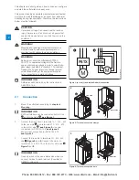


4.
Connect the control supply voltage (100-250V
50/60Hz) to terminal 1 and 2 .
5.
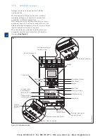
Connect the functional earth (terminal 22), to an
earthing point close to the softstarter.
See Figure 4.
The earthing is not a protective earth, it is a
functional earth. The earthing cable should be
as short as possible. Maximum length is 0.5 m.
The earthing cable should be connected to the
mounting pla
te were the softstarter is mounted,
which should also be earthed.
6.
Look at the diagram,
see Figure 5
, and connect
the start/stop circuits: terminal 13, 14, 18, 19 and
20/21, with the internal 24V DC terminal. When
using internal 24 V DC (terminals 20 or 21), the
terminals 18 and 19 should be connected to each
other. For external control circuit voltage,
see chapter
5.1.2.3 Start and Stop - terminals
13, 14, 18, 19, 20, 21.
WARNING
Use 24V DC only when you connect terminal 13, 14,
15, 16 and 17. Other voltages can cause damage
to the softstarter and the warranty will no longer be
valid. For more information about terminal 15, 16 and
17, see chapter
5.1.2.4 Programmable inputs -
terminals 15, 16 and 17.
7.
Connect terminals 4, 5, 6, 7, 8, 9, 10, 11 and 12
to use the signal output relays. These are potential
free contacts for maximum 250 V AC, 1.5 A AC-15
and 30 V DC, 5 A DC-12.
See Figure 6.
8.
Check that the operational voltage and control
supply voltage corresponds to the softstarter
ratings.
9.
Switch on the control supply voltage.
10.
The green “Ready” LED will flash on the HMI, as in
Figure 7.
11.
After switching on the softstarter the language
settings will appear on the display, choose your
language and press selection softkey “OK”. The
HMI will now download language data from the
softstarter. Which may take several minutes. When
this is completed the HMI will switch to Home view.
12.
Configure applicable parameters as given in
chapter 7 Functions
or use the assistants as
described in
chapter 2.2 Configuration
.
Figure 4:
Functional earth, terminal 22.
4
1SFC132081M0201
5
22
L1
L2
L3
N
KM1
1L1 3L2 5L3
2T1 4T2 6T3
U V W
19 20
18
15 16 17
14
13
2
1
21
M
3
Stop
Star
24 V DC
t
L N
12
11
10
9
8
7
6
5
4
22
20
14
18 19
13
Start
Stop
1SFC132081M0201
Figure 5: Circuit diagram PSTX30...PSTX370
(Fuse and contactor version)
6
22
L1
L2
L3
N
1L1 3L2 5L3
2T1 4T2 6T3
U V W
19 20
18
15 16 17
14
13
2
1
21 22
M
3
Stop
Star
24 V DC
t
L N
12
11
10
9
8
7
6
5
4
22
20
14
18 19
13
Start
Stop
1SFC132081M0201
Figure 6: Circuit diagram PSTX30...PSTX370 ( MCCB version)
PSTX
L
100-250V
50/60 Hz
K4
K4
K4
Start Stop Reset In1 In2 DGND DND +24V GND
N
7
1SFC132081M0201
Figure 7: Flashing “Ready” LED
2
Phone: 800.894.0412 - Fax: 888.723.4773 - Web: www.clrwtr.com - Email: [email protected]
Содержание PSTX30
Страница 4: ...Phone 800 894 0412 Fax 888 723 4773 Web www clrwtr com Email info clrwtr com...
Страница 6: ...Phone 800 894 0412 Fax 888 723 4773 Web www clrwtr com Email info clrwtr com...
Страница 10: ...1 Phone 800 894 0412 Fax 888 723 4773 Web www clrwtr com Email info clrwtr com...
Страница 16: ...2 Phone 800 894 0412 Fax 888 723 4773 Web www clrwtr com Email info clrwtr com...
Страница 26: ...3 Phone 800 894 0412 Fax 888 723 4773 Web www clrwtr com Email info clrwtr com...
Страница 32: ...4 Phone 800 894 0412 Fax 888 723 4773 Web www clrwtr com Email info clrwtr com...
Страница 44: ...5 Phone 800 894 0412 Fax 888 723 4773 Web www clrwtr com Email info clrwtr com...
Страница 64: ...6 Phone 800 894 0412 Fax 888 723 4773 Web www clrwtr com Email info clrwtr com...
Страница 124: ...7 Phone 800 894 0412 Fax 888 723 4773 Web www clrwtr com Email info clrwtr com...
Страница 128: ...8 Phone 800 894 0412 Fax 888 723 4773 Web www clrwtr com Email info clrwtr com...
Страница 131: ...9 Phone 800 894 0412 Fax 888 723 4773 Web www clrwtr com Email info clrwtr com...
Страница 132: ...9 Phone 800 894 0412 Fax 888 723 4773 Web www clrwtr com Email info clrwtr com...
Страница 142: ...10 Phone 800 894 0412 Fax 888 723 4773 Web www clrwtr com Email info clrwtr com...
Страница 145: ...11 Phone 800 894 0412 Fax 888 723 4773 Web www clrwtr com Email info clrwtr com...


