background image

Softstarters Type PSTX30...PSTX370

Installation and commissioning manual

1SFC132081M0201 EN, Rev A

Phone: 800.894.0412 - Fax: 888.723.4773 - Web: www.clrwtr.com - Email: [email protected]

Содержание PSTX30

Страница 1: ...Softstarters Type PSTX30 PSTX370 Installation and commissioning manual 1SFC132081M0201 EN Rev A Phone 800 894 0412 Fax 888 723 4773 Web www clrwtr com Email info clrwtr com...

Страница 2: ...she is kindly asked to notify us as soon as pos sible The data contained in this manual is intended solely for the product description and is not to be deemed to be a state ment of guaranteed propert...

Страница 3: ...he transportation company or the ABB reseller office immediately Do not lift the softstarter by the connection bars as this can do damage to the softstarter Saftey notes In this user manual these symb...

Страница 4: ...Phone 800 894 0412 Fax 888 723 4773 Web www clrwtr com Email info clrwtr com...

Страница 5: ...ting 5 Connection 6 Human machine interface HMI 7 Functions 8 Communication 9 Maintenance 10 Troubleshooting 11 Wiring diagrams 12 Revisions Softstarters Type PSTX Installation and commissioning manua...

Страница 6: ...Phone 800 894 0412 Fax 888 723 4773 Web www clrwtr com Email info clrwtr com...

Страница 7: ...nstallation and commissioning manual 1 2 Intended audience 9 1 3 Revision notes and other documents 9 1 4 Acronyms and abbreviations 9 1 4 Acronyms and abbreviations 9 1 Introduction Phone 800 894 041...

Страница 8: ...3 Index Index of the content of this manual 1 1 2 Installation and commissioning manual Short form The Softstarters Type PSTX30 PSTX370 Installation and comissioning manual Short form contains brief i...

Страница 9: ...ns The acronyms and abbreviations described in table 3 are used in this manual Table 3 Acronyms and abbreviations Acronym abbreviation Description BP By pass DOL Direct on line EOL Electronic overload...

Страница 10: ...1 Phone 800 894 0412 Fax 888 723 4773 Web www clrwtr com Email info clrwtr com...

Страница 11: ...nnection 12 2 2 Configuration 14 2 2 1 Basic set up 14 2 2 2 Application set up 14 2 3 How to start stop the motor 15 2 Quick start Phone 800 894 0412 Fax 888 723 4773 Web www clrwtr com Email info cl...

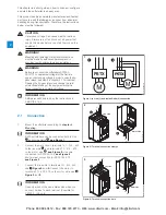
Страница 12: ...o operational voltage INFORMATION ABB personell have to obey the instructions in ABB CISE 15 4 2 1 Connection 1 Mount the softstarter according to chapter 4 Mounting INFORMATION PSTX softstarters can...

Страница 13: ...AC 15 and 30 V DC 5 A DC 12 See Figure 6 8 Check that the operational voltage and control supply voltage corresponds to the softstarter ratings 9 Switch on the control supply voltage 10 The green Read...

Страница 14: ...on keys to select Yes or No and then press Save 7 Press and then Press Done to finish the Basic setup For more settings enter Application set up 2 2 2 Application set up 1 Find the Assistants menu fro...

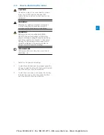
Страница 15: ...open the by pass relays see step 6 in chapter 2 1 Connection Opening the by pass relays is necessary to avoid unintentional starting of the equipment while it is being connected to operational voltag...

Страница 16: ...2 Phone 800 894 0412 Fax 888 723 4773 Web www clrwtr com Email info clrwtr com...

Страница 17: ...ctions 19 3 1 5 Softstarter overview 20 3 1 6 Type designation 21 3 1 7 Environmental influence 21 3 1 8 Specifications 21 3 2 Technical data 22 3 2 1 General 22 3 2 2 Technical data for external keyp...

Страница 18: ...e softstarter has several advanced motor protection features as standard Bypass Softstarter range PSTX30 370 have integrated by pass components For PSTX210 370 this is a three phase by pass contactor...

Страница 19: ...nt imbalance warning Over voltage warning Under voltage warning EOL time to trip warning EOL warning Total Harmonic Distortion THD warning Voltage imbalance warning Power factor underload warning Curr...

Страница 20: ...this interface Overview See Figure 8 Ready Run Fault Protection Com1 Com2 4T2 2T1 6T3 3L2 1L1 5L3 PSTX L 100 250V 50 60 Hz K4 K5 K6 Start Stop In1 In2 DGND 24V GND N In0 8 1SFC132081M0201 Figure 8 So...

Страница 21: ...ications General data Description Degree of protection Main circuit PSTX30 105 IP10 PSTX142 370 IP00 Degree of protection Supply and control circuit PSTX30 105 IP20 PSTX142 370 IP20 Operating position...

Страница 22: ...play type Status indicating LEDs Power on Green Protection Yellow Fault Red Ambient temperature Storage 25 C to 70 C 13 F to 158 F Operation 25 C to 60 C 13 F to 140 F Degree of protection IP66 UL app...

Страница 23: ...200 355 450 370 640 PSTX370 690 70 200 257 355 355 450 600 370 640 PSTX30 370 Temp 40 C 104 oF 4 Ie in 10 sec Motor power when connected In Line Motor power when connected Inside Delta Full load curr...

Страница 24: ...2 in 4x M6 1 4 in 1SFC132081M0201 Figure 10 Dimensions PSTX30 105 PSTX 142 170 1SFB536268G1011 1SFC132081M0201 11 220 mm 8 7 in 235 mm 9 3 in 377 mm 14 8 in 165 mm 6 5 in 7 5 mm 0 3 in 361 mm 14 2 in...

Страница 25: ...51 mm 17 8 in 10 5 mm 0 4 in 389 mm 15 3 in 5 mm 0 2 in 151 mm 5 9 in M6 1 4 in 12 1SFC132081M0201 200 mm 7 9 in 258 mm 10 2 in 43 7 mm 1 7 in 4x 19 6 mm 0 8 in 6x Figure 12 Dimensions PSTX210 370 3 P...

Страница 26: ...3 Phone 800 894 0412 Fax 888 723 4773 Web www clrwtr com Email info clrwtr com...

Страница 27: ...g 29 4 2 2 Minimum distance to wall front 29 4 2 3 Minimum enclosure size 30 4 2 4 Maximum mounting angle 30 4 2 5 Dimensions and drilling plan 30 4 2 6 Detachable keypad 30 4 2 6 1 Mounting Detachabl...

Страница 28: ...at all items are included according to the delivery note See Table 1 Delivery note Check the softstarter as well as the packaging In case of damages please contact the transport company or the ABB res...

Страница 29: ...f damage to property Ensure that no liquids dust or conductive parts enter the softstarter WARNING If you do not obey these instructions this can cause the softstarter to become overheated or not oper...

Страница 30: ...drilling plan For dimensions and drilling plan see chapter 3 2 6 Dimensions Drilling plan is also printed on the box WARNING Risk of damage to property Ensure that no liquids drilling swarf dust or co...

Страница 31: ...nnector through the drilled hole See 3 in Figure 21 Fasten the plastic screw nut on the threaded network connector with 2 Nm 17 7 lb in 3 Remove the RJ45 plug see 4 Connect one end of the network cabl...

Страница 32: ...4 Phone 800 894 0412 Fax 888 723 4773 Web www clrwtr com Email info clrwtr com...

Страница 33: ...t and Stop terminals 13 14 18 19 20 21 37 5 1 2 4 Programmable inputs terminals 15 16 and 17 39 5 1 2 5 Programmable output relay K4 terminals 4 5 and 6 41 5 1 2 6 Programmable output relay K5 termina...

Страница 34: ...een the softstarter and the motor since this can cause current peaks which can burn the thyristors in the softstarter If such capacitors are to be used they should be connected on the line side of the...

Страница 35: ...Flexible 10 70 mm Rigid flexible 2x6 2x35 mm max 30 mm 1 181 in max 30 mm 1 181 in max 10 mm 0 394 in M10 28 Nm 240 lb in Using connection bars max 24 mm 0 945 in max 22 mm 0 866 in max 8 mm 0 315 in...

Страница 36: ...PSTX370 should be earthed using the terminals as shown in Figure 27 one connection is sufficient Connect the cable to an earthing point close to the softstarter The cable should be as short as possib...

Страница 37: ...x 0 6 mm 0 138 x 0 024 in M3 L 100 250V 50 60 Hz K4 K5 K6 Start Stop In0 In1 In2 GND 24V N 1SFC132081M0201 A conventional circuit with auxiliary relay is also possible See Figure 30 Tightening torque...

Страница 38: ...5 mm2 AWG 12 24 0 5 Nm 4 3 lb in 3 5 x 0 6 mm 0 138 x 0 024 in M3 L 100 250V 50 60 Hz K4 K5 K6 Stop In0 In1 In2 GND 24V N 1SFC132081M0201 Tightening torques and cable dimensions 31 PSTX L 100 250V 50...

Страница 39: ...0 5 Nm 4 3 lb in 3 5 x 0 6 mm 0 138 x 0 024 in M3 L 100 250V 50 60 Hz K4 K5 K6 Start Stop In0 In1 In2 GND 24V N 1SFC132081M0201 Tightening torques and cable dimensions 0 2 2 5 mm2 2x0 2 1 5 mm2 0 2 2...

Страница 40: ...rminal 4 0 2 2 5 mm2 2x0 2 1 5 mm2 0 2 2 5 mm2 2x0 2 1 5 mm2 AWG 12 24 0 5 Nm 4 3 lb in 3 5 x 0 6 mm 0 138 x 0 024 in M3 L 100 250V 50 60 Hz K4 K5 K6 Start Stop In0 In1 In2 GND 24V N 1SFC132081M0201 T...

Страница 41: ...sions 0 2 2 5 mm2 2x0 2 1 5 mm2 0 2 2 5 mm2 2x0 2 1 5 mm2 AWG 12 24 0 5 Nm 4 3 lb in 3 5 x 0 6 mm 0 138 x 0 024 in M3 5 L 100 250V 50 60 Hz K4 K5 K6 Start Stop In0 In1 In2 GND 24V N 1SFC132081M0201 5...

Страница 42: ...esistance and the wire resistance are added together The resulting systematic errors must be taken into account when adjusting the tripping device A jumper must be connected between the terminals T2 a...

Страница 43: ...ter and it shall refer to the functional ground The analogue output can be selected to show I A U V P kW P Hp Q kVAr S kVA cos Phi Motor temp SCR temp and Energy kWh If the analogue output is used the...

Страница 44: ...5 Phone 800 894 0412 Fax 888 723 4773 Web www clrwtr com Email info clrwtr com...

Страница 45: ...dd information screens to Home view 52 6 3 2 2 Edit information screens in Home view 52 6 3 2 3 Display slot 52 6 3 2 4 Scale value range 53 6 3 3 Active faults protections and warnings 53 6 4 Menu sc...

Страница 46: ...When softstarter is controlling operational voltage Ue during start or stop ramp Steady light When full operational volt age Ue is on at Top of Ramp Protection 3 Yellow Off When the softstarter has n...

Страница 47: ...softstarter between local control from the HMI and remote control from hardwire input or fieldbus See 3 in Figure 46 i key The i key is an information key for the HMI and provides context related inf...

Страница 48: ...vigation keys to select number the selected number is highlighted black Then Press or to change the value of the selected number Press Save to save See Figure 48 On off switch Select 1 or 0 on or off...

Страница 49: ...1 2 Press Select to select Parameters menu 3 Press Select to select Complete list 4 Press Select to select 01 Motor rated current Ie 5 Press Edit to edit the rated current in Motor rated current Ie 6...

Страница 50: ...long as Jog is pressed For intormation about Motor jog see chapter 6 2 4 Motor jog To reach the Motor Jog follow this path in menu Menu u Motor jog 6 2 1 Start key The start key is the start switch fo...

Страница 51: ...ss Menu to enter the Motor jog menu and then select Motor Jog Use and to jog forward and backwards See 4 in Figure 53 The motor will start and accelerate to the rated speed according to the set parame...

Страница 52: ...shown in the Home view Use the Navigation keys to change value Press Save to save the value Value is shown by 3 in Figure 55 6 3 Options screen 6 3 1 Overview In Options screen it is possible to chan...

Страница 53: ...e Home view unit name See 4 in Figure 56 6 3 3 Active faults protections and warnings Path in menu Options u Active faults protections Options u Active warnings Active faults protections warnings are...

Страница 54: ...Shows all parameters for advanced setup 6 4 1 2 Favorites Choose favorite parameter functions for quick selection 6 4 1 3 Modified Shows modified parameters Use Navigation keys to navigate in the subm...

Страница 55: ...evel 28 06 Torque profile start 28 07 Torque finish 28 08 Torque tune 28 09 Torque ctrl gain 28 10 Torque PI intergration time 28 11 Torque slip 28 12 Torque diff 28 13 Torque filter time For full par...

Страница 56: ...om defaults Press Select and then Edit to edit the parameter which differs from default Press Save to save and return to previous menu Or press Cancel to return to previous state without saving Figure...

Страница 57: ...ssistants menu by pressing Menu and select Assistants with the Navigation keys Press Select to enter the Assistants menu Basic set up Use the Navigation keys to select Basic set up Press Select to ent...

Страница 58: ...i key to see information about the Protection Press Back to return to Protections log menu Warnings Use the Navigation keys to select a Warning and press Details to read details about the Warning Nam...

Страница 59: ...an store two backups Use the Navigation keys to select a earlier backup and press Replace to replace a backup 6 4 4 2 Uploading of parameters 1 After finishing the download of parameters detach the HM...

Страница 60: ...aults Home view layout Will be available in a future release Reset fault log Reset all parameters Settings can be set with Keypad and Fieldbus communication HMI Softstarter Softstarter FW version 1 11...

Страница 61: ...nu The icon symbols a wrench 3 Press the Select to enter the Settings menu 4 Highlight the first alternative and press Select and then Edit to enter Language settings 5 Use and to select language See...

Страница 62: ...ay settings For navigation see Figure 75 The Display settings includes all display configurations of the softstarter To change the Display settings Press Edit to enter the setting level Press Save to...

Страница 63: ...to select the data which is to be reset 4 Press Yes to reset or press No to cancel Confirmation of reset will be displayed as Done on the display Reset operating data Reset operating data is divided...

Страница 64: ...6 Phone 800 894 0412 Fax 888 723 4773 Web www clrwtr com Email info clrwtr com...

Страница 65: ...urrent limit 75 7 7 Kick start 76 7 8 Slow speed 77 7 9 Motor heating 78 7 10 Sequence start 79 7 11 Automatic restart 80 7 12 Inputs outputs 81 7 12 1 Digital inputs DI 82 7 12 2 Relay outputs 84 7 1...

Страница 66: ...parameters Set the parameters via HMI With the HMI Keypad parameters can be set as individual parameter settings or as a selection of predefined parameters for different applications The HMI complete...

Страница 67: ...rt a motor by controlling the output voltage or torque The Start ramp ends and goes into Top of ramp state when the output voltage reaches 100 voltage Settable start functions are Voltage start ramp T...

Страница 68: ...r Motor Current Ie is configured with the following parameters Parameter Description Setting range Default value 01 01 Motor Current Ie Set the nominal current of the motor For good performance it is...

Страница 69: ...l to full voltage The actual time to reach the Top of ramp state also depends on the current which means that the time to reach Top of ramp can be longer than the set Voltage ramp time If the motor is...

Страница 70: ...ers Parameter Description Setting range Default value 02 02 Stop mode Set to voltage ramp No ramp Voltage ramp Torque ramp DC Brake Soft brake No ramp 02 05 Stop ramp end level Sets the level from whe...

Страница 71: ...amp start the rotational speed is constant if the set torque curve corresponds to the actual load curve The output voltage will not increase linearly as when using the voltage start ramp see Figure 80...

Страница 72: ...level from where the start ramp initiates 10 99 30 02 04 Start ramp time Sets the time it takes for the voltage to reach 100 1 120s 10s 03 05 Torque limit level Sets the limit for the torque during s...

Страница 73: ...takes for the voltage to reach end level 1 120 s 10 s 28 05 Step down level Sets the level from where the stop ramp initiates 10 100 80 28 07 Torque finish Sets the operational torque for Torque star...

Страница 74: ...tion Setting range Default value 02 02 Stop mode Set to No ramp No ramp Voltage stop ramp Torque stop ramp Voltage ramp 7 5 Stand still brake The Stand still brake breakes the output to the motor and...

Страница 75: ...nt reaches the second current limit the softstarter will behave as for the normal current limit Dual current limit can be used as a back up function to prevent overheating Ramp current limit When the...

Страница 76: ...the following parameters Parameter Description Setting range Default value 04 01 Kick start Enables a voltage peak at the beginning of the start ramp On Off Off 04 02 Kick start level Sets the level o...

Страница 77: ...ltage applied to the motor and the motor stops For navigation see chapter 6 2 4 Motor Jog Slow speed is configured with the following parameters Parameter Description Setting range Default value 02 07...

Страница 78: ...up the engine without starting it Motor heating is configured with the following parameters Parameter Description Setting range Default value 02 07 Pre start function Set to Motor heating Off Motor h...

Страница 79: ...age start ramp Torque start ramp Full voltage ramp Voltage start ramp 08 04 Start ramp time seq 1 08 32 seq 2 08 62 seq 3 Sets the time it takes for the voltage to reach 100 1 120 s 10 s 08 05 Start r...

Страница 80: ...with a fixed time interval between each During the time between each restart the start digital input signal is ignored If the fault still remain by the time a restart is made this will be seen as a fa...

Страница 81: ...ay output 1 Analog output To use an extension IO provides the same possibilities to use all the softstarters functions as for the programmable internal IO Available Extension IO TBD For example an Ext...

Страница 82: ...reverse While the digital input is high the motor will slowly move in the reverse direction Motor heating While the digital input is high the motor heating is active Stand still brake While the digit...

Страница 83: ...rse User defined protection Emergency mode Fieldbus disable control Start 1 Start 2 Start 3 Reset 10 02 In1 function Same as In0 None 10 03 In2 function Same as In0 None External digital Inputs extens...

Страница 84: ...t is continuously shorted to common Internal relay outputs internal IO is configured with the following parameters Parameter Description Setting range Default value 10 04 K4 function Function of progr...

Страница 85: ...rrent output can be set by a configuration parameter AO reference in the softstarter The selection of voltage or current must be set to adapt to the analog meter or the PLC The settings are 0 10V volt...

Страница 86: ...e Sets the min analog output value 0 0 1000000 0 External Analog output Extension IO is configured with the following parameters Description Description Setting range Default value 11 13 1AO0 referenc...

Страница 87: ...100 The softstarter has a 3 wire PT100 input that can be combined and share terminals with the PTC input The trip temperature is set by the user The maximum trip temperature is 250 and lowest is 25 Th...

Страница 88: ...ation the fieldbus interface must be enabled before any action can be taken Fieldbus address If the softstarter is going to be used with fieldbus communication set a fieldbus address for the softstart...

Страница 89: ...which baudrates that can be used for different protocols See separate Table below 12 10 FB parity Sets parity for Anybus Modbus RTU No parity Odd parity Even parity Even parity 12 11 FB stop bits Sele...

Страница 90: ...3 Sets the AI 3 programmable analog input signal Phase L3 current 12 25 Fieldbus AI 4 Sets the AI 4 programmable analog input signal Max phase curent 12 26 Fieldbus AI 5 Sets the AI 5 programmable an...

Страница 91: ...can be mapped to a relay output or and a fieldbus signal For each supervision function there is a parameter for assigning the corresponding event to one or more Event groups In PSTX there are seven E...

Страница 92: ...ion is activated When any of the protections signals a risk of damage the following basic actions will be performed Protection LED will light up The type of event is displayed The type of event is log...

Страница 93: ...ction is configured with the following parameters Parameter Description Setting range Default value 13 06 Locked rotor level Set the locked rotor trip level 0 5 8 0 x Ie 4 0 x Ie 13 07 Locked rotor tr...

Страница 94: ...s the operation of this protection Off Stop manual Stop auto Indication Off 7 15 5 Power factor underload protection The power factor has fallen below the normal level The Power factor underload prote...

Страница 95: ...rational in the Standby state Over voltage protection is configured with the following parameters Parameter Description Setting range Default value 15 01 Over voltage level Sets the Over voltage trip...

Страница 96: ...his protection detects if the phases are connected in the wrong order and then prevents the engine from starting Check the phase sequence on the line side to L1 L2 L3 Phase reversal protection is conf...

Страница 97: ...protection belongs to Eventgroup 0 6 2 16 11 Voltage outputs op Sets the operation of this protection Off Stop manual Stop auto Indication Off 7 15 14 Temperature sensors 7 15 14 1 External thermal se...

Страница 98: ...Sets the PT100 reset temperature 50 250 40 17 06 PT100 out Specifies the Event groups this protection belongs to Eventgroup 0 6 2 17 07 PT100 op Sets the operation of this protection Off Stop manual S...

Страница 99: ...r the set current limit Check starting conditions and parameters Too long current limit protection is configured with the following parameters Parameter Description Setting range Default value 18 08 T...

Страница 100: ...up 0 6 2 19 04 Fieldbus failure op Sets the operation of this protection Off Stop manual Stop auto Indication Off 7 15 20 Extension IO failure protection This protection detacts if there is communicat...

Страница 101: ...warning A warning signal will be given if the motor temperature exceeds the settable warning level of max temperature Electronic overload warning is configured with the following parameters Parameter...

Страница 102: ...1 0 x Ie 0 4 x Ie 21 02 Curr underload trip time Sets the time that the current has to be under the Warning level to trip 0 30 s 5 s 21 03 Curr underload delay time Sets the time delay after Top of r...

Страница 103: ...range Default value 22 01 Over voltage level User configured warning level in Volts 208 850 V 208 V 22 02 Over voltage trip time User configured time until warning in seconds 0 1 100 0 s 1 0 s 22 03 O...

Страница 104: ...ription Setting range Default value 23 01 EOL time to trip time Sets how long time before the EOL protection trips the warning is activated 1 1000 s 5 s 23 02 EOL time to trip out Specifies the Event...

Страница 105: ...umber of starts out Specifies the Event groups this warning belongs to Eventgroup 0 6 4 24 03 Number of starts Enables Number of starts limits warning level Off On Off 7 16 14 Fans fault warning A war...

Страница 106: ...ults are detected these basic actions will be performed Fault LED will light up The type of event is displayed The type of event is logged on the event list Faults cannot be configured in other way th...

Страница 107: ...o a direct stop If the the Fire pump is enabled and a fault is detected the softstarter will try to run the motor according to the start and stop signals ignore safety and continue to run regardless o...

Страница 108: ...ge Default value 25 05 Open circuit thyr out Specifies the Event groups this fault belongs to Eventgroup 0 6 1 25 06 Open circuit thyr out Sets the operation of this fault Stop manual Stop auto Stop m...

Страница 109: ...Heat sink over temp op Sets the operation of this fault Stop manual Stop auto Stop manual 7 17 1 6 Unspecified fault This fault is a grouping of several internal faults that are quite unlikely and do...

Страница 110: ...ongs to Eventgroup 0 6 1 26 04 Bad network op Set the operation of this fault Stop manual Stop auto Stop manual 7 17 2 3 Low supply voltage fault Too low control supply voltage on terminals 1 and 2 A...

Страница 111: ...eed functions and the motor is connected inside delta Faulty usage fault is configured with the following parameters Parameter Description Setting range Default value 26 09 Faulty usage out Specifies...

Страница 112: ...the time between start signal and beginning of diagnostic measurements 0 65535 ms 245 ms 7 18 4 TOR relay delay time TBD TOR relay delay time is configured with the following parameters Parameter Desc...

Страница 113: ...ng voltage ramp it shall be set to 80 Depending on the load it can be necessary to adjust the step down level Step down level is configured with the following parameters Parameter Description Setting...

Страница 114: ...on should not be selected again If this is done all the tuning will be reset to the default settings for the selected application Enter the Assistants menu Find the Assistants menu by pressing right S...

Страница 115: ...pump 10 10 40 30 4 5 Voltage ramp Torque ramp Hydraulic pump 10 30 30 3 Voltage ramp No ramp Lift Elevator 10 30 30 3 5 Voltage ramp No ramp Piston compressor 5 50 30 3 Voltage ramp No ramp Scroll co...

Страница 116: ...orward Fast jog Jog Creep 0 0 Jog 05 02 Slow speed fwd strenght 10 100 0 0 50 05 03 Slow speed reverse Fast jog Jog Creep 0 0 Jog 05 04 Slow speed rev strength 10 100 0 0 50 06 Motor heating 06 01 Mot...

Страница 117: ...defined protection Emergency mode Fieldbus disable control Start 1 Start 2 Start 3 0 130 Reset 10 02 In1 function 0 15 0 131 None 10 03 In2 function 0 15 0 132 None 10 04 K4 function None Run Top of r...

Страница 118: ...O2 function 0 15 0 155 None 11 12 2DO3 function 0 15 0 156 None 11 13 1AO0 reference 0 10 mA 0 20 mA 4 20 mA 0 10 V 0 157 4 20 mA 11 14 1AO0 type Motor current A Mains voltage V Active power kW Active...

Страница 119: ...5 Event group 3 status 12 20 Fieldbus DI 9 0 32 0 166 Event group 4 status 12 21 Fieldbus DI 10 0 32 0 167 Event group 5 status 12 22 Fieldbus AI 1 None Phase L1 current Phase L2 current Active power...

Страница 120: ...factor underload op Off Stop Manual Stop Automatic Indication 0 0 Off 14 11 Curr imb level 10 80 0 61 80 14 12 Curr imb trip time 1 30 s 0 63 10 s 14 13 Curr imb delay time 1 30 s 0 62 30 s 14 14 Curr...

Страница 121: ...19 01 HMI failure out 0 127 0 100 0000010 19 02 HMI failure op Off Stop Manual Stop Automatic Indication Switch of HMI control 0 0 Off 19 03 Fieldbus failure out 0 127 0 97 0000010 19 04 Fieldbus fai...

Страница 122: ...Shunt fault op Stop Manual Stop Automatic 0 0 Stop Manual 25 03 Short circuit out 0 127 0 50 0000001 25 04 Short circuit fault op Stop Manual Stop Automatic 0 0 Stop Manual 25 05 Open circuit thyr ou...

Страница 123: ...ss trip angle 1 1 240 0 12 28 26 Phase loss trip angle 2 1 240 0 0 70 28 27 Bad network quality On Off 0 35 On 28 28 Low supply voltage On Off 0 37 On 28 29 High current fault On Off 0 38 On 28 30 Shu...

Страница 124: ...7 Phone 800 894 0412 Fax 888 723 4773 Web www clrwtr com Email info clrwtr com...

Страница 125: ...1 Instructions 126 8 2 2 Required accessories 126 8 3 ABB Fieldbus plug interface option 126 8 3 1 Instructions 126 8 3 2 Required accessories 126 8 4 Mini USB interface 127 8 Communication Phone 800...

Страница 126: ...cting the ABB Fieldbus Plug Adapter FBPA used for fieldbus communication With this interface it is possible to control the softstarter retreive status information as well as upload and download parame...

Страница 127: ...s PCs The USB interface is located on the front of the detachable HMI With this interface it is possible to control the softstarter retreive status information as well as upload and download parameter...

Страница 128: ...8 Phone 800 894 0412 Fax 888 723 4773 Web www clrwtr com Email info clrwtr com...

Страница 129: ...9 9 1 Regular maintenance 130 9 2 Service and repair 130 9 Maintenance Phone 800 894 0412 Fax 888 723 4773 Web www clrwtr com Email info clrwtr com...

Страница 130: ...nce This can be checked at voltage free state Check the Real Time Clock and adjust if necessary In case of a fault or if a fault can not be reset see chapter 10 9 2 Service and repair In case the PSTX...

Страница 131: ...9 Phone 800 894 0412 Fax 888 723 4773 Web www clrwtr com Email info clrwtr com...

Страница 132: ...9 Phone 800 894 0412 Fax 888 723 4773 Web www clrwtr com Email info clrwtr com...

Страница 133: ...10 3 Overview of faults protections and warnings 137 10 4 Protection indication shown on screen 138 10 5 Fault indication shown on screen 139 10 6 Warning indication shown on screen 141 Phone 800 894...

Страница 134: ...so be found in this chapter 10 2 Troubleshooting Table 1 Troubleshooting Status Possible cause Solution Motor humming starts without given start signal By pass relay closed due to inaccurate handling...

Страница 135: ...al control mode Check connections for start and stop Check that start and stop command is not given at the same time Check that the keypad is not in Local Control mode Press the R L key to change to R...

Страница 136: ...otor current Inside Delta connection If the softstarter is connected Inside Delta the phase currents displayed are 58 1 3 of the motor current Displayed current in screen is not stable The motor is to...

Страница 137: ...lure protection X X X X X X X X X X Extension IO failure protection X X X X X X X X X X HMI failure protection X X X X X X X X X X Limit number of starts X Faults Phase loss fault X X X X X X X X High...

Страница 138: ...rt the motor and check the main currents and voltage Current imbalance protection Current imbalance between the phases Restart the motor and check the main currents and voltage Over voltage protection...

Страница 139: ...n removed Place back the HMI again Limit number of starts The softstarter has exceeded the pre set limited number of starts Wait for the next start interval For parameter setting see chapter 7 Functio...

Страница 140: ...on operational voltage on terminals L1 L2 and L3 If same fault remains contact your ABB Sales Office Unspecified fault N A Disconnect and reconnect the supply voltage Us and make a restart If same fau...

Страница 141: ...ctor underload warning The power factor has decreased below the adjustable value during continuous operation Current underload warning The motor current has fallen below the warning level Check that t...

Страница 142: ...10 Phone 800 894 0412 Fax 888 723 4773 Web www clrwtr com Email info clrwtr com...

Страница 143: ...ams 11 1 Circuit diagram PSTX 144 11 1 3 Circuit diagram PSTX30 PSTX170 IEC version 144 11 1 4 Circuit diagram PSTX30 PSTX170 UL version 144 Phone 800 894 0412 Fax 888 723 4773 Web www clrwtr com Emai...

Страница 144: ...T1 4T2 6T3 1L1 3L2 5L3 V5 V6 K2 V4 V3 V2 V1 Ct1 Ct2 Ct3 2 T1 1 L1 11 1 4 Circuit diagram PSTX30 PSTX170 UL version CAUTION Terminal 22 is a function earth it is not a protective earth It shall be conn...

Страница 145: ...11 Phone 800 894 0412 Fax 888 723 4773 Web www clrwtr com Email info clrwtr com...

Страница 146: ...isions is done on this document Document number Revision Chapter Description Date 1SFC132081M0201 A First release 2014 06 27 12 12 Revisions Phone 800 894 0412 Fax 888 723 4773 Web www clrwtr com Emai...

Отзывы: