Modifications reserved
Page 31/50
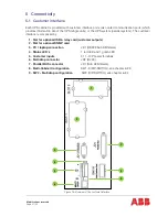
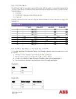
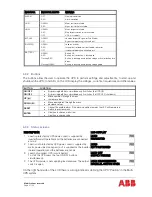
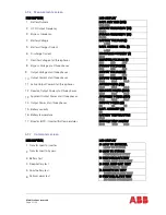
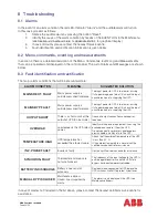
INDICATOR
INDICATOR STATUS
MEANING
ALARM
OFF
RED
No alarm condition
Alarm condition
LINE 1
GREEN
RED
Mains rectifier available
Mains rectifier not available
LINE 2
GREEN
RED
OFF
Mains bypass available
Main bypass not ok or not available
UPS is turned off
BYPASS
GREEN
OFF
Load on bypass (Bypass-or Eco-Mode)
Bypass not operating (switched-off)
INVERTER
GREEN
RED
OFF
Load on inverter
Inverter fault or load not transferable to inverter
Inverter not operating (switched-off)
BATTERY
GREEN
RED
Flashing RED
Flashing GREEN
Battery OK
Battery fault or battery is discharged
Battery in discharge and battery voltage critical or battery fuse
open
Battery in discharge and battery voltage good
6.3.2
Buttons
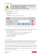
The buttons allow the user to operate the UPS to perform settings and adjustments, to start-up and
shutdown the UPS, to monitor on the LCD display the voltages, currents, frequencies and other values.
BUTTON
FUNCTION
ON/OFF
ON/OFF
•
By pressing both keys simultaneously it switches the UPS ON
•
By pressing both keys simultaneously it switches the UPS OFF (shutdown)
UP (
)
•
Move upwards through the menu
•
Increase values
DOWN (
)
•
Move downwards through the menu
•
decrease values
RESET
•
Cancel the audible alarm. If the alarm condition remains the LED will remain red
•
Return to previous menu
ENTER
•
Confirms a chosen menu item
•
Confirms a chosen value
6.3.3
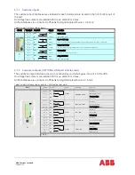
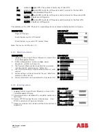
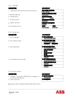
Status screens
DESCRIPTION
LCD-DISPLAY
1
Load is protected by UPS power. Load is supplied by
inverter(Normal Operation) and the batteries are connected
and o.k.
LOAD
PROTECTED
P01
2
Load is not protected by UPS power. Load is supplied by
mains power (load on bypass) or it is supplied by the inverter
(normal operation) and the batteries are not o.k.
LOAD
NOT PROTECTED
P01
3
Load not supplied. UPS is switched off.
To start the UPS press the two ON/OFF buttons
simultaneously.
LOAD OFF
SUPPLY FAILURE
P01
4
The UPS/module is not supplying load anymore. The output
switch is open
LOAD DISCONNECTED
PARALLEL SWITCH OPEN
P01
On the right hand side of the LCD there is a 3-digit indicator defining the UPS “Position” in the Multi-
UPS system.
Содержание PowerWave 33 Series 3
Страница 1: ... Copyright 2017 ABB All rights reserved User Manual PowerWave 33 Series 3 60 120 kW ...
Страница 46: ...Modifications reserved Page 46 50 10 Attachments 10 1 Technical data sheet ...
Страница 48: ......
Страница 49: ... Copyright 2016 ABB All rights reserved Technical data sheet PowerWave 33 Serie 3 60 120 kW ...

