background image

4 Repair

4.6.1. Replacement of motor, axis 1

301

3HAC026876-001  Revision: C     

© Copyri

ght 

200

6-2008 ABB.

 All rights reserved.

Removal, motor axis 1

The procedure below details how to remove motor, axis 1. 

Standard toolkit 


The content is defined in 
section 

Standard toolkit 

on page 394

.

Calibration Pendulum 
toolkit

3HAC15716-1

Complete kit that also 
includes operating 
manual.

Other tools and 
procedures may be 
required. See 
references to these 
procedures in the 
step-by-step instruc-
tions below. 


These procedures include 
references to the tools 
required. 

Circuit Diagram 

3HAC025744-001

See chapter 

Circuit 

diagram

.

Equipment, etc. 

Spare part no.

Art. no. 

Note 


 Action 

Note

1.

DANGER!

Turn off all electric power, hydraulic and pneumatic 
pressure supplies to the robot!

For Foundry Prime robots: Do not turn off the air 
pressure to motors and SMB.

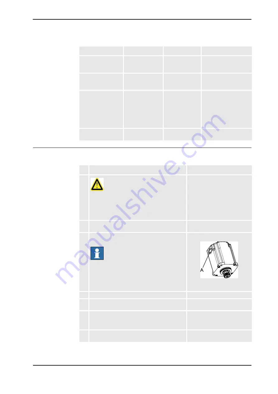
2. Remove the cover for connector access on top of 

the motor by unscrewing its four attachment screws. 

3. Remove the cable gland cover at the cable exit by 

unscrewing its two attachment screws. 

NOTE!

Make sure the gasket is not damaged! 

xx0200000199

 A: Cable gland cover 

4. Disconnect all connectors beneath the motor cover.   

5. Apply lifting tool, motor axis 1, 4, 5  to the motor. 

Art. no. is specified in 

Required 

equipment on page 300

.

6. In order to release the brakes, connect the 24 VDC 

power supply. 

Connect to connector R2.MP1 

+: pin 2 

 -: pin 5 

7. Remove the motor by unscrewing its four  

attachment screws  and plain washers. 

Shown in the figur

Location of 

motor on page 300

.

Continued

Continues on next page

Содержание IRB 6640 - 130/3.2

Страница 1: ...Product manual Articulated robot IRB 6640 180 2 55 IRB 6640 235 2 55 IRB 6640 205 2 75 IRB 6640 185 2 8 IRB 6640 130 3 2 IRB 6640ID 200 2 55 IRB 6640ID 170 2 75 M2004 ...

Страница 2: ......

Страница 3: ... 2008 ABB All rights reserved Product manual IRB 6640 180 2 55 IRB 6640 235 2 55 IRB 6640 205 2 75 IRB 6640 185 2 8 IRB 6640 130 3 2 IRB 6640ID 200 2 55 IRB 6640ID 170 2 75 M2004 Document ID 3HAC026876 001 Revision C ...

Страница 4: ...sons or property fitness for a specific purpose or the like In no event shall ABB be liable for incidental or consequential damages arising from use of this manual and products described herein This manual and parts thereof must not be reproduced or copied without ABB s written permission and contents thereof must not be imparted to a third party nor be used for any unauthorized purpose Contravent...

Страница 5: ...ormation labels 29 1 3 Safety related instructions 30 1 3 1 Safety signals general 30 1 3 2 DANGER Moving robots are potentially lethal 32 1 3 3 DANGER First test run may cause injury or damage 33 1 3 4 WARNING The brake release buttons may be jammed after service work 34 1 3 5 WARNING The unit is sensitive to ESD 35 1 3 6 WARNING Safety risks during work with gearbox oil 36 2 Installation and com...

Страница 6: ...3 6 Inspection oil level gearbox axis 6 125 3 3 7 Inspection balancing device 128 3 3 8 Inspection cable harness 133 3 3 9 Inspection of air hoses Foundry Prime 138 3 3 10 Inspection information labels 139 3 3 11 Inspection mechanical stop axis 1 142 3 3 12 Inspection additional mechanical stops 144 3 3 13 Inspection damper axes 2 5 146 3 3 14 Inspection signal lamp option 148 3 4 Replacement Chan...

Страница 7: ...eplacement of balancing device old and new 285 4 5 5 Unloading the balancing device old and new 294 4 5 6 Restoring the balancing device 297 4 6 Motors 300 4 6 1 Replacement of motor axis 1 300 4 6 2 Replacement of motor axis 2 306 4 6 3 Replacement of motor axis 3 313 4 6 4 Replacement of motor axis 4 320 4 6 5 Replacement of motor axis 5 IRB 6640 326 4 6 6 Replacement of motor axis 5 IRB 6640ID ...

Страница 8: ...394 7 7 Special tools 395 7 8 Lifting equipment and lifting instructions 398 8 Spare Part List IRB 6640 399 8 1 Base frame 399 8 2 Spare parts Balancing device 401 8 3 Frame to lower arm 405 8 4 Lower arm to upper arm 407 8 5 Upper arm including wrist unit motors ax 3 6 IRB 6640 and IRB 6640ID 409 8 6 Cable harness and SMB unit 412 9 Circuitdiagrams 415 9 1 Introduction 415 Índice 417 ...

Страница 9: ... repair maintenance work Organization of chapters The manual is organized in the following chapters Chapter Contents Safety Safety information that must be read through before performing any installation or service work on the robot Contains general safety aspects as well as more specific information on how to avoid personal injuries and damage to the product Installation and commis sioning Requir...

Страница 10: ... manual SpotPack DressPack IRB 6640 3HAC028638 001 Product manual Controller IRC5 3HAC021313 001 Operating manual IRC5 with Flexpendant 3HAC16590 1 Operating manual Calibration pendulum 3HAC16578 1 Operating manual Service Information System 3HAC025709 001 Application manual Additional axes and stand alone controller 3HAC021395 001 Technical reference manual System parameter 3HAC17076 1 Applicatio...

Страница 11: ...ures including spare parts Additional procedures if any calibration decommissioning Reference information article numbers for documentation referred to in Product manual procedures lists of tools safety standards Part list Foldouts or exploded views Circuit diagrams Technical reference manuals The following manuals describe the robot software in general and contain relevant reference information R...

Страница 12: ...d at those having first hand operational contact with the robot that is production cell operators programmers and trouble shooters The group of manuals includes Emergency safety information General safety information Getting started IRC5 IRC5 with FlexPendant RobotStudio Introduction to RAPID Trouble shooting for the controller and robot Continued ...

Страница 13: ...nclude references to equipment spare parts tools etc required for the different actions in the procedure The equipment is marked with italic text in the procedures and completed with a reference to the section where the equipment is listed with further information that is article number dimensions The denomination in the procedure for the component or attachment point corresponds to the denominati...

Страница 14: ...How to read the product manual 3HAC026876 001 Revision C 12 Copyright 2006 2008 ABB All rights reserved ...

Страница 15: ...s important to attend to before performing any service work on the robot These are applicable for all service work and are found in section General safety information specific safety information pointed out in the procedure at the moment of the danger How to avoid and eliminate the danger is either detailed directly in the procedure or further detailed in separate instructions found in section Saf...

Страница 16: ...tion and handling of the industrial robot described in the applicable documents for example Operating Manual IRC5 with FlexPendant M2004 Product Manual Connection of external safety devices Apart from the built in safety functions the robot is also supplied with an interface for the connection of external safety devices Via this interface an external safety function can interact with other machine...

Страница 17: ...t be crossed before admittance must be set up in front of the robot s working space Light beams or sensitive mats are suitable devices Turntables or the like should be used to keep the operator out of the robot s working space The axes are affected by the force of gravity when the brakes are released In addition to the risk of being hit by moving robot parts you run the risk of being crushed by th...

Страница 18: ...lt in burns too Removed parts may result in collapse of robot WARNING Take any necessary measures to ensure that the robot does not collapse as parts are removed e g secure the lower arm with fixtures if removing motor axis 2 Safety risk Description Cable packs are sensitive to mechanical damage CAUTION The cable packs are sensitive to mechanical damage They must be handled with care especially th...

Страница 19: ...safely turn off tools such as milling cutters etc Make sure that guards remain closed until the cutters stop rotating It should be possible to release parts by manual operation valves Safe design Grippers end effectors must be designed so that they retain workpieces in the event of a power failure or a disturbance of the controller CAUTION Ensure that a gripper is prevented from dropping a workpie...

Страница 20: ... to pneumatic and hydraulic systems Residual energy Residual energy may be present in these systems After shutdown particular care must be taken The pressure in pneumatic and hydraulic systems must be released before starting to repair them Safe design Gravity may cause any parts or objects held by these systems to drop Dump valves should be used in case of emergency Shot bolts should be used to p...

Страница 21: ...rried out professionally and in accordance with the applicable safety regulations Care must be taken at all times Qualified personnel Corrective maintenance must only be carried out by qualified personnel who are familiar with the entire installation as well as the special risks associated with its different parts Extraordinary risks If the working process is interrupted extra care must be taken d...

Страница 22: ...om an external source The mains supply mains switch The transformers The power unit The control power supply 230 VAC The rectifier unit 400 480 VAC and 700 VDC Note Capacitors The drive unit 700 VDC The drive system power supply 230 VAC The service outlets 115 230 VAC The customer power supply 230 VAC The power supply unit for additional tools or special power supply units for the machining proces...

Страница 23: ...mension the fence or enclosure to enable it to withstand the force created if the load being handled by the robot is dropped or released at maximum speed Determine the maximum speed from the maximum velocities of the robot axes and from the position at which the robot is working in the work cell see Product Specification Description Robot Motion Also consider the maximum possible impact caused by ...

Страница 24: ...e extinguishing 3HAC026876 001 Revision C 22 Copyright 2006 2008 ABB All rights reserved 1 2 3 2 Fire extinguishing NOTE Use a CARBON DIOXIDE CO2 extinguisher in the event of a fire in the robot system robot or controller ...

Страница 25: ...eased manually by pushing the brake release buttons on the robot How to release the brakes is detailed in section Manually releasing the brakes on page 61 The robot arm may be moved manually on smaller robot models but larger models may require using an overhead crane or similar Increased injury Before releasing the brakes make sure that the weight of the arms does not increase the pressure on the...

Страница 26: ...m its function How to test The function of the holding brake of each axis motor may be checked as detailed below 1 Run each robot axis to a position where the combined weight of the robot arm and any load is maximized max static load 2 Switch the motor to the MOTORS OFF position with the Operating mode selector on the controller 3 Check that the axis maintains its position If the robot does not ch...

Страница 27: ...6 001 Revision C Copyright 2006 2008 ABB All rights reserved 1 2 3 5 Risk of disabling function Reduced speed 250 mm s NOTE Do not change Transm gear ratio or other kinematic system parameters from the FlexPendant or a PC This will affect the safety function Reduced speed 250 mm s ...

Страница 28: ... him her when entering the robot s working space This is to prevent anyone else taking control of the robot without the programmer knowing Enabling device The enabling device is a manually operated constant pressure push button which when continuously activated in one position only allows potentially hazardous functions but does not initiate them In any other position hazardous functions are stopp...

Страница 29: ...ntrol panel The robot s speed is limited to max 250 mm s when the operating mode selector is in position manual mode with reduced speed This should be the normal position when entering the working space The position manual mode with full speed 100 may only be used by trained personnel who are aware of the risks that this entails Pay attention to the rotating axes of the robot Keep a distance to th...

Страница 30: ...reserved 1 2 3 8 Signal lamp optional Description A signal lamp with an yellow fixed light can be mounted on the robot as a safety device Function The lamp is active in MOTORS ON mode Further information Further information about the MOTORS ON MOTORS OFF mode may be found in the controller documentation ...

Страница 31: ...o the product contain space for adding a fourth language underneath the three standard languages English German and French Add a local language to the label by Using a transparent sticker over the standard label with text added in a fourth language Drawings detailing the design text figure dimensions of the standard labels can be ordered from ABB Notice that each label is identified according to t...

Страница 32: ...h for example contact with high voltage electrical units explosion or fire risk risk of poisonous gases risk of crushing impact fall from height etc warning WARNING Warns that an accident may occur if the instructions are not followed that can lead to serious injury possibly fatal and or great damage to the product It applies to warnings that apply to danger with for example contact with high volt...

Страница 33: ...lectrostatic discharge ESD symbol indicates electrostatic hazards which could result in severe damage to the product Note NOTE Note symbols alert you to important facts and conditions Tip TIP Tip symbols direct you to specific instructions where to find additional information or how to perform a certain operation in an easier way Symbol Designation Signification Continued ...

Страница 34: ...ction Note 1 Before attempting to run the robot make sure all emergency stop equipment is correctly installed and connected Emergency stop equipment such as gates tread mats light curtains etc 2 Usually the hold to run function is active only in manual full speed mode To increase safety it is also possible to activate hold to run for manual reduced speed with a system parameter The hold to run fun...

Страница 35: ... to take into consideration before the first test run Elimination Follow the procedure below when performing the first test run after a service activity repair installation or maintenance Action 1 Remove all service tools and foreign objects from the robot and its working area 2 Install all safety equipment properly 3 Make sure all personnel are standing at a safe distance from the robot that is o...

Страница 36: ...se the power is turned on while a brake release button is jammed in depressed position the affected motor brake is released This may cause serious personal injuries and damage to the robot Elimination To eliminate the danger after service work has been performed inside the SMB recess follow the procedure below Action 1 Make sure the power is turned off 2 Remove the push button guard if necessary 3...

Страница 37: ...ot grounded may potentially transfer high static charges This discharge may destroy sensitive electronics Elimination Location of wrist strap button The wrist strap button is located in the right corner as shown in the illustration below xx0500002171 Action Note 1 Use a wrist strap Wrist straps must be tested frequently to ensure that they are not damaged and are operating correctly 2 Use an ESD p...

Страница 38: ...the opening Do not overfill the gearbox when filling Do not overfill Overfilling of gearbox oil can lead to internal over pressure inside the gearbox which in turn may damage seals and gaskets completely press out seals and gaskets prevent the robot from moving freely Make sure not to overfill the gearbox when filling with oil After filling check the correct oil level Do not mix types of oil Mixin...

Страница 39: ...erved 2 Installation and commissioning 2 1 Introduction General This chapter contains information for installing the robot to the working site More detailed technical data such as load diagram permitted extra loads equipment and location of extra loads equipment may be found in the Product Specification for the robot ...

Страница 40: ...er way than method 1 or 2 can seriously damage the robot If the robot is incorrectly transported and the instructions are not followed the robot is not covered by the warranty and ABB will not accept any compensation claim Method 1 Transportation according to method 1 is strongly recommended by ABB xx0800000030 Always follow these instructions when transporting an ABB robot according to method 1 A...

Страница 41: ...B robot according to method 2 Always read and follow the instructions in section Securing the robot Always place the robot in the ABB recommended transport position for robot with tool detailed in sub section Transport position with a mounted tool Always use the recommended transport support detailed in sub section Recommended transport support IRB7600 IRB66XX xx0800000037 A Transport Support B He...

Страница 42: ...transportation precautions 3HAC026876 001 Revision C 40 Copyright 2006 2008 ABB All rights reserved IRB6620 xx0800000036 A Transport Support B Hexagon socket head cap screw M10x50 C Threaded bar M10x280 D Nut M10 Continued Continues on next page ...

Страница 43: ...cautions 41 3HAC026876 001 Revision C Copyright 2006 2008 ABB All rights reserved Transport position with a transport support All transportation of the robot with tool must follow these instructions IRB 7600 IRB 66XX xx0800000040 Continued Continues on next page ...

Страница 44: ...2 Installation and commissioning 2 2 Robot transportation precautions 3HAC026876 001 Revision C 42 Copyright 2006 2008 ABB All rights reserved IRB 6620 xx0800000041 Continued Continues on next page ...

Страница 45: ...precautions 43 3HAC026876 001 Revision C Copyright 2006 2008 ABB All rights reserved Recommended transport support Always use the recommended transport support when transporting a robot with tool IRB 7600 IRB 66XX xx0800000039 Continued Continues on next page ...

Страница 46: ...2 Installation and commissioning 2 2 Robot transportation precautions 3HAC026876 001 Revision C 44 Copyright 2006 2008 ABB All rights reserved IRB 6620 xx0800000038 Continued ...

Страница 47: ...erved 2 3 Securing the robot General This section describes how to secure the robot using the transport support DANGER Releasing the brakes is a hazardous action that may cause injury and damage property It must be done with great care and only when absolutely necessary Securing the robot xx0800000062 Continues on next page ...

Страница 48: ...ed tool CAUTION Do not try to jog the robot to the exact position max distance 1mm 3 Use the brake release for axis 3 to reach the final resting position on the transport support see section Manually releasing the brakes See attachment point for the specific robot in section Transport position with a mounted tool 4 Tightening all the attachment screws A and B in figure with the brake release for a...

Страница 49: ... Make sure the lifting device used is suitable to handle the weight of the robot as specified in Weight robot on page 47 4 If the robot is not installed directly it must be stored as described in Storage conditions robot on page 48 5 Make sure the expected operating environment of the robot conforms to the specifica tions as described in Operating conditions robot on page 48 6 Before taking the ro...

Страница 50: ...g conditions robot The table below shows the allowed operating conditions for the robot Force Endurance load operation Max load emergency stop Force xy 8 5 kN 20 4 kN Force z 15 0 9 0 kN 15 0 20 0 kN Torque xy 20 1 kNm 45 2 kNm Torque z 5 1 kNm 10 6 kNm Requirement Value Note Min levelity 0 5 mm Max tilt 5 The limit for the maximum load on the robot is reduced if the robot is tilted Contact ABB fo...

Страница 51: ...tallation procedure 49 3HAC026876 001 Revision C Copyright 2006 2008 ABB All rights reserved Protection classes robot The table below shows the protection class of the robot Equipment Protection class Robot IP 67 Cooling fans option IP 54 Continued ...

Страница 52: ...2 IRB 6640ID 200 2 55 170 2 75 The illustration below shows the unrestricted working range Measurements for the different robot variants are shown as A to F in the illustration below xx0600003396 Robot model A B C D E F IRB 6640 2 55 3013 mm 284 mm 2550 mm 903 mm 1119 mm 1814 mm IRB 6640 2 75 3219 mm 268 mm 2755 mm 961 mm 1252 mm 1999 mm IRB 6640 2 8 3261 mm 533 mm 2800 mm 1004 mm 1324 mm 2061 mm ...

Страница 53: ...640 2 55 2550 mm IRB 6640 2 75 2755 mm IRB 6640 2 8 2800 mm IRB 6640 3 2 3200 mm IRB 6640ID 2 55 2550 mm IRB 6640ID 2 75 2755 mm Axis Type of motion Range of movement Note 1 Rotation motion 170 to 170 Movement range can be set to 220º to 220º option 561 1 2 Arm motion 85º to 65º 3 Arm motion 70º to 180º 4 Wrist motion 300º to 300º IRB 6640ID the range of movement is the combined value for axis 4 a...

Страница 54: ...mum combination of axes 4 and 6 NOTE There are limitations of the range of movement with a DressPack SpotPack application fitted to the robot See product manual SpotPack DressPack IRB 6640 Art no in References 6 Turn motion IRB 6640 360º to 360º default 96 revolutions IRB 6640ID 300º to 300º 300º max 1 Axis Type of motion Range of movement Note Continued ...

Страница 55: ...d standing still the robot is not stable in the whole working area Moving the arms will displace the center of gravity which may cause the robot to tip over Do not change the robot position before securing it to the foundation Stabililty The figure below shows the robot in its shipping position which also is its most stable position xx0600003400 WARNING The robot is likely to be mechanically unsta...

Страница 56: ...at available special aids are used This section describes how to attach the fork lift equipment to the robot Fork lift device set The fork lift device set is fitted to the robot as shown in the figure below xx0600002910 Required equipment A Fork lift pocket B Attachment screw M20x50 quality 8 8 2 pcs x 4 Equipment etc Art no Note Fork lift device set 3HAC025040 003 Standard toolkit The content is ...

Страница 57: ...illustration below shows the position of the robot when lifting it with fork lift xx0600003401 Action Note 1 Move the robot to the position as shown in the figure above NOTE No load is permitted on the robot Release the brakes if required as detailed in section Manually releasing the brakes on page 61 2 DANGER Turn off all electric power hydraulic and pneumatic pressure supplies to the robot For F...

Страница 58: ...are always used or replacements of equivalent quality M20x50 quality 8 8 Attachment points on the robot are shown in the figure below xx0600002927 A Attachment holes for fork lift 4 NOTE For Cleanroom robots protective plates are applied between the fork lifting pocket and the robot base in order to prevent from particle emission when lifting xx0800000042 Parts A Fork lifting pocket B Protective p...

Страница 59: ...ng torque 300 Nm 6 Insert the fork lift forks into the pockets 7 CAUTION The robot weighs up to 1450 kg depending on variant See lifting instruction for details All lifting equipment used must be sized accordingly NOTE When the robot is equipped with forklift pockets an extra weight of 90 kg must be added 8 Carefully lift the robot and move it to its installation site NOTE Move the robot with low ...

Страница 60: ...th the label attached to the robot s lower arm Attachment points The figure below shows how to attach the roundslings to the robot xx0600003455 IRB 6640 standard Lifting instruction 3HAC027647 001 A Roundsling robot 2 5 m 4 pcs B Roundsling upper arm 2 m Note Make a loop around the upper arm and wrap the roundsling twice around the upper arm Do not stretch C Lifting eye M20 4 pcs Note Fit lifting ...

Страница 61: ...aged B Roundsling upper arm 2 m NOTE Make a loop around the upper arm and wrap the roundsling twice around the upper arm Do not stretch C Lifting eye M20 4 pcs NOTE Fit lifting eyes in the rear holes D Positions for cellular plastic NOTE Do not lift without See procedure below for more specific information where to apply the cellular plastic Sling type Qty Lifting capacity Length Note Roundsling r...

Страница 62: ...mission while lifting put for example a 20 mm thick cellular plastic sheet around the places on the robot where the lifting equipment may rub against the paint Put the 20 mm cellular plastic sheet as extra protection in the following places Around the upper arm Lower arm Balancing device Around motor axis 2 Not shown in figure xx0800000060 Protective cellular plastic sheets at A Upper arm B Lower ...

Страница 63: ...te 1 The internal brake release unit is located on the frame beside motor axis 1 The internal brake release unit is equipped with six buttons for controlling the axes brakes The buttons are numbered according to the numbers of the axes If the robot is not connected to the controller power must be supplied to the connector R1 MP according to section Supplying power to connector R1 MP on page 62 2 D...

Страница 64: ...r R1 MP If the robot is not connected to the controller power must be supplied to connector R1 MP in the robot base in order to enable the brake release buttons on the robot Action Note 1 DANGER Incorrect connections such as supplying power to the wrong pin may cause all brakes to be released simultaneously 2 Supply 0V on pin 12 and 24V on pin 11 xx0600002937 Continued ...

Страница 65: ...fting base plate Equipment Art no Note Lifting eye M16 3HAC14457 4 3 pcs Lifting slings 3 pcs Length approx 2 m A Attachment holes for lifting eyes x3 Action Note 1 CAUTION The base plate weighs 353 kg All lifting equipment used must be sized accordingly 2 Fit the lifting eyes in the three lifting holes Shown in the figure Hole con figuration on page 63 3 Fit the lifting slings to the eyes and to ...

Страница 66: ...ecuring the base plate 3HAC026876 001 Revision C 64 Copyright 2006 2008 ABB All rights reserved 2 5 5 Securing the base plate General This section details how to secure the base plate Base plate dimensions xx0100000105 Continues on next page ...

Страница 67: ...on and commissioning 2 5 5 Securing the base plate 65 3HAC026876 001 Revision C Copyright 2006 2008 ABB All rights reserved xx0400000715 A Four holes for alternative clamping 4x Ø18 Continued Continues on next page ...

Страница 68: ...s attachment holes 4 pcs Equipment Art no Note Base plate 3HAC12937 9 Includes guide sleeves 3HAC12937 3 levelling screws 9ADA120 79 attachment screws and washers for securing the robot to the base plate A drawing of the base plate itself may be ordered from ABB Robotics Standard toolkit The content is defined in section Standard toolkit on page 394 Other tools and procedures may be required See r...

Страница 69: ...tion to the robot work location using the three grooves in the base plate Shown in the figure Base plate grooves and holes on page 66 4 Lift the base plate to its mounting position Detailed in section Lifting the base plate on page 63 5 Use the base plate as a template and drill 16 attachment holes as required by the selected bolt dimension If possible observe the recommenda tions specified in sec...

Страница 70: ...te The illustration below shows the robot base fitted to the base plate xx0600002933 Attachment screws The table below specifies the type of securing screws and washers to be used for securing the robot to the base plate foundation A Robot attachment bolts and washers 8 pcs M24 x 100 B Orienting grooves in the robot base and in the base plate C Levelling screws Note Remove before the robot base is...

Страница 71: ...location 3 Fit two guide sleeves to the guide sleeve holes in the base plate NOTE One of the guide sleeve holes is elongated 4 Guide the robot gently using two M24 screws while lowering it into its mounting position Make sure the robot base is correctly fitted onto the guide sleeves 5 Fit the bolts and washers in the base attachment holes Specified inAttachment screws on page 68 Shown in the figur...

Страница 72: ...n C 70 Copyright 2006 2008 ABB All rights reserved Hole configuration base The illustration below shows the hole configuration used when securing the robot xx0600003403 Cross section guide sleeve hole The illustration below shows the cross section of the guide sleeve holes xx0600003404 Continued ...

Страница 73: ...lacement of cable harness Cleanroom on page 207 Location of cable harness attachments Cleanroom The cable harness attachments are located as shown in the figure below xx0800000022 Required equipment A Shelf B Gripping clamp C Side bracket balancing cylinder D Lower bracket E Gripping clamp F Bracket for cable clamp G Gripping clamp H Gripping clamp J Bracket for cable clamp K Cable guide L Connect...

Страница 74: ...hese procedures in the step by step instructions below These procedures include references to the tools required Equipment Part no Note Action Note 1 DANGER Turn off all electric power hydraulic and pneumatic pressure supplies to the robot For Foundry Prime robots Do not turn off the air pressure to motors and SMB 2 Fit the shelf to the frame with its attachment screws Lock screws with locking liq...

Страница 75: ...uired equipment on page 71 xx0800000008 Parts A Shelf B Cover C Attachment screws M8x16 quality 8 8 A2F 2 pcs D Washer 2 holes E Gripping clamp 4 Fit the side bracket balancing cylinder with its attachment screws Lock screws with locking liquid The screws are supplied with the kit Locking liquid is specified in Required equipment on page 71 xx0800000010 Parts A Side bracket balancing cylinder B At...

Страница 76: ...page 71 xx0800000010 Parts A Lower bracket B Gripping clamp C Washer 2 holes D Attachment screws M8x16 quality 8 8 A2F 2 pcs 6 Then attach the lower bracket with the gripping clamp already fitted to the side bracket balancing cylinder with its attachment screws Lock screws with locking liquid The screws are supplied with the kit Locking liquid is specified in Required equipment on page 71 xx080000...

Страница 77: ...erent depending on robot variant See figure to the right xx0800000014 A SW 2 55 B SW 2 75 8 Fit the two brackets for cable clamp on the lower arm with its attachment screws Lock screws with locking liquid Locking liquid is specified in Required equipment on page 71 xx0800000019 Parts A Bracket for cable clamp B Attachment screws M12x25 quality 8 8 A3F 2 2 pcs Action Note Continued Continues on nex...

Страница 78: ...e supplied with the kit Locking liquid is specified in Required equipment on page 71 xx0800000021 Parts A Gripping clamp B Bracket for gripping clamp Action Note Action Note 1 DANGER Turn off all electric power hydraulic and pneumatic pressure supplies to the robot For Foundry Prime robots Do not turn off the air pressure to motors and SMB 2 Fit the bracket for cable clamp on top of the armhouse w...

Страница 79: ...it Locking liquid is specified in Required equipment on page 71 xx0800000023 Parts A Armhouse B Locking nut M8 C Washer D Bracket for cable clamp E Gripping clamp F Washer 2 holes G Attachment screws M8x25 quality 8 8 A2F 2 pcs 4 Fit the cable guide on the side of the armhouse with its attachment screws Lock screws with locking liquid The screws are supplied with the kit Locking liquid is specifie...

Страница 80: ...8 ABB All rights reserved 5 Fit the connection plate axis 3 with its attachment screws Lock screws with locking liquid The screws are supplied with the kit Locking liquid is specified in Required equipment on page 71 xx0800000026 Parts A Connection plate axis3 B Attachment screws M10x16 quality 8 8 A3F 2 pcs Action Note Continued ...

Страница 81: ...following places turning disk armhouse frame Additional cables from base to upper arm may not be fitted to Cleanroom robots NOTE The robot IRB 6640ID is delivered with DressPack and there may not be any additional equipment fitted to the robot except at the turning disk and the frame Illustration fitting of extra equipment on lower arm The illustrations below shows the mounting holes available for...

Страница 82: ...ll rights reserved xx0600003405 xx0600003406 Robot variant A B C IRB 6640 2 55 2240 mm 520 mm 1075 mm IRB 6640 2 75 2445 mm 725 mm 1280 mm IRB 6640 2 8 2240 mm 520 mm 1075 mm IRB 6640 3 2 2445 mm 725 mm 1280 mm IRB 6640ID 2 55 2240 mm 520 mm 1075 mm IRB 6640ID 2 75 2445 mm 725 mm 1280 mm Continued Continues on next page ...

Страница 83: ... be fitted on the upper arm of IRB 6640ID and Cleanroom robots xx0600003414 xx0200000196 Robot variant A B C IRB 6640 2 55 400 mm 13 mm 40 mm IRB 6640 2 75 500 mm 13 mm 30 mm IRB 6640 2 8 400 mm 13 mm 40 mm IRB 6640 3 2 500 mm 13 mm 30 mm IRB 6640ID 2 55 400 mm 13 mm 40 mm IRB 6640ID 2 75 500 mm 13 mm 30 mm Robot variant A B IRB 6640 2 55 1142 mm 200 mm IRB 6640 2 75 1142 mm 200 mm IRB 6640 2 8 13...

Страница 84: ... 3HAC026876 001 Revision C 82 Copyright 2006 2008 ABB All rights reserved Illustration fitting of extra equipment on frame The illustration below shows the mounting holes available for fitting extra equipment on the frame xx0600003416 Continued Continues on next page ...

Страница 85: ...robot 83 3HAC026876 001 Revision C Copyright 2006 2008 ABB All rights reserved Illustration fitting on turning disk The illustration below shows the mounting holes available for fitting equipment on the turning disk xx0200000197 Continued Continues on next page ...

Страница 86: ...opyright 2006 2008 ABB All rights reserved xx0500001580 Fastener quality When fitting tools on the turning disk see the figures above only use screws with quality 12 9 When fitting other equipment standard screws with quality 8 8 may be used Turning disk unit for robot versionIRB 6640ID Continued ...

Страница 87: ... 2 However cooling fans for axes 1 and 2 can not be combined The cabling for the fans is available as separate cabling for axis 1 or 2 including only connections for the cooling fans on axes 1 or 2 Installation of this cabling is detailed in section Installation separate fan cabling axis 1 or 2 on page 89 Location of cooling fans The fans are installed on the motors axes 1 2 as shown in the figure...

Страница 88: ...te Cooling fan 3HAC15374 1 Cabling cooling fans axes 1 or 2 3HAC023599 001 Choose this cabling if equipping the robot with cooling fans on axis 1 or 2 Plate for customer connections 3HAC025778 001 An additional connection plate must be fitted to the robot base if not already installed The plate is shown in the figure Plate for customer connections at base on page 87 Additional cabling to and insid...

Страница 89: ...lkit The content is defined in section Standard toolkit on page 394 Circuit diagram 3HAC025744 001 See chapter Circuit diagram Other tools and procedures may be required See references to these procedures in the step by step instructions below These procedures include references to the tools required Equipment Art no Note A Plate for customer connections B Attachment screws 3 pcs M6x16 quality 8 8...

Страница 90: ...d damaging the surfaces of the motor when fitting the fanbox turn the connector to the correct position axis 1 groove pointing inwards as shown in the figure Cooling fan on page 86 Position for axis 2 is shown in the same figure Shown in the figure Cooling fan on page 86 3 Temporarily lift the motor cabling out of the way of the current motor to make room for the fanbox 4 Fit the parts of the fanb...

Страница 91: ...ic power hydraulic and pneumatic pressure supplies to the robot For Foundry Prime robots Do not turn off the air pressure to motors and SMB 3 Remove the rear cover plate from the robot base Shown in the figure Location of cooling fans on page 85 4 Remove the cable bracket A Shown in the figure Separate cabling for axis 1 or 2 on page 88 5 Fit the plate for customer connections if not already fitte...

Страница 92: ...tor R3 FAN2 to the fan of axis 1or 2 NOTE Fans on both axis 1 and 2 can not be used at the same time 9 Connect the connector R1 SW2 3 to the base of the robot Make sure that the cabling run through the frame and base is not twisted and runs freely from the robot cabling 10 Refit the rear cover plate to the robot base 11 Install additional cabling to and inside the controller Also make adjustments ...

Страница 93: ...ents and overloading motors gears and structure CAUTION Incorrect defined loads may result in operational stops or major damage on the robot References Load diagrams permitted extra loads equipment and their positions are specified in the Product Specification The loads must also be defined in the software as detailed in Operating manual IRC5 with FlexPendant Stop time and braking distances Robot ...

Страница 94: ... risk that it may collide with other objects its working space should be limited The working range of the following axis may be restricted Axis 1 hardware mechanical stop and software Axis 2 hardware mechanical stop and software Axis 3 hardware mechanical stop and software This section describes how to install hardware that restricts the working range Notice that adjustments must also be made in t...

Страница 95: ...stops axis 1 The illustration below shows the mounting position of the stop pin and one of the additional mechanical stops available for axis 1 xx0600002938 Required equipment A Movable mechanical stop B Attachment screw plus washer M12 x 40 quality 12 9 2 pcs C Fixed mechanical stop D Mechanical stop pin axis 1 Equipment etc Art no Note Mechanical stop for axis 1 7 5 3HAC025204 003 Includes attac...

Страница 96: ...oundry Prime robots Do not turn off the air pressure to motors and SMB 2 Fit the additional mechanical stop to the frame according to the figure Mechanical stops axis 1 on page 93 Tightening torque 120 Nm 3 NOTE To utilize the option 561 1 Extended working range axis 1 the software working range limitations must be re defined The motion configuration parameter arm rob1_1 Upper Joint Bound and arm ...

Страница 97: ...the same Required equipment Installation mechanical stops axis 2 The procedure below details how to fit the mechanical stops for axis 2 to the robot An assembly drawing is also enclosed with the product A Additional stops axis 2 B Fixed stop axis 2 Equipment etc Art no Note Mechanical stop set axis 2 3HAC020885 001 Includes six stops attachment screws washers and assembly drawings Standard toolkit...

Страница 98: ...own in the figure Mechanical stops axis 2 on page 95 3 The software working range limitations must be re defined to correspond to the changes in the mechanical limitations of the working range The system parameters that must be changed in RobotWare 5 0 Upper joint bound and Lower joint bound are further detailed in Technical reference manual System parameters 4 WARNING If the mechanical stop is de...

Страница 99: ...ustration below shows the mounting position of the mechanical stops on axis 3 The figure shows IRB 7600 but the principle is the same xx0300000048 Required equipment A Additional mechanical stops B Fixed mechanical stop Equipment etc Art no Note Mechanical stop set axis 3 3HAC13128 1 Includes six stops one with 80 restriction 3HAC12708 3 use when limitation angle 80 and five with 20 3HAC12708 1 at...

Страница 100: ...o the robot For Foundry Prime robots Do not turn off the air pressure to motors and SMB 2 Mount and tighten the additional stops in a row starting from the fixed stop Shown in the figure Mechanical stops axis 3 on page 97 3 NOTE The software working range limitations must be re defined to correspond to the changes in the mechanical limitations of the working range The system parameters that must b...

Страница 101: ...s on page 99 Fan cables option Handles supply to and feedback from any cooling fan on the robot Specified in the table Fan cables robot base to control cabinet option on page 100 Customer cables option Handles communication with equipment fitted on the robot by the customer including databus communication low voltage signals and high voltage power supply protective ground See the product manual fo...

Страница 102: ...om the robot base to the inside of the cabinet If equipping the robot with cooling fans use the cabling specified below The cables for cooling fans listed below are used together with a distributing cable also specified below Robot cable power 22 m 3HAC11818 3 Robot cable power 30 m 3HAC11818 4 Cable Art no Cable Art no Robot cable signal shielded 7 m 3HAC7998 1 Robot cable signal shielded 15 m 3H...

Страница 103: ...h off the overpressure in motors and serial measurement compartment during cooling down of robot after it has been switched off When turning off a cleaning cell we recommend that the humid air inside a cell is ventilated out to avoid that the humid air is sucked into gearboxes for example due to the raised vacuum when cooled down Environmental conditions The table below details the environmental c...

Страница 104: ... balancing device and serial measurement board cavity The robots are prepared with hoses to the motors and the serial measurement board cavity to enable pressurizing of them WARNING The robot must be pressurized also when it is switch off to avoid that the humid environmental air is sucked into the motors when cooling down Action Note 1 Connect a compressed air hose to air connector on robot base ...

Страница 105: ...t should be exposed to direct high pressure jet of water The sealings between the moving parts on the wrist should not be exposed to direct or rebounding high pressure jet of water Protection points at the wrist joints The illustration below shows points that are particularly sensitive to water spray xx0600002792 A Axis 5 bearing support side B Axis 5 bearing gear side C Axis 6 mounting flange gea...

Страница 106: ...tors and serial measurement compartment during cooling down of robot after it has been switched off NOTE To reduce the risk for corrosion due to condensation in gearboxes it is recommendable that the robot is running with high speed on each axes at least on one occasion each hour This is to lubricate the gearbox cavities NOTE When turning off a cleaning cell we recommend that the humid air is vent...

Страница 107: ...ork possible to perform without cracking the paint The robot is painted with four layers of polyurethane paint The last layer being a varnish over labels in order to simlify cleaning Cleanroom parts being replaced must be replaced with parts designed for use in Cleanroom environments Cleanroom class 5 Particle emission from the robot fulfill Cleanroom class 5 standard according to DIN EN ISO 14644...

Страница 108: ...2 Installation and commissioning 2 9 1 Additional installation procedure Cleanroom 3HAC026876 001 Revision C 106 Copyright 2006 2008 ABB All rights reserved ...

Страница 109: ...including intervals and refers to procedures for the activities Each procedure contains all information required to perform the activity that is required tools and materials The procedures are gathered in different sections and divided according to the maintenance activity Safety information Before any service work is commenced it is extremely important that all safety information is observed Ther...

Страница 110: ...t and the working conditions of the robot Calendar time specified in months regardless of whether the robot system is run or not Operating time specified in operating hours More frequent running of the robot means more frequent maintenance activities SIS specified by the robot s SIS Service Information System A typical value is given for a typical work cycle but the value will differ depending on ...

Страница 111: ... axis 2 on page 117 Inspection Axis 3 gear oil level 12 mths 1 Inspection oil level gearbox axis 3 on page 119 Inspection Axis 4 gear oil level 12 mths Inspection oil level gearbox axis 4 on page 121 Inspection Axis 5 gear oil level 12 mths Inspection oil level gearbox axis 5 on page 123 Inspection Axis 6 gear oil level 12 mths 1 Inspection oil level gearbox axis 6 on page 125 Inspection Balancing...

Страница 112: ... SIS or typically 96 mths Replacement of gearbox axis 1 Replacement Axis 2 gearbox As specified by the SIS or typically 96 mths Replacement of gearbox axis 2 Replacement Axis 3 gearbox As specified by the SIS or typically 96 mths Replacement of gearbox axis 3 on page 361 Replacement Axis 4 gearbox 5 96 mths 2 Replacement of upper arm on page 260 Replacement Axis 5 gearbox 6 96 mths 2 Replacement o...

Страница 113: ... below specifies the required maintenance activities and intervals for common optional equipment Maintenance of other external equipment for the robot is detailed in separate documentation Activities and intervals Foundry Prime The table below specifies the required maintenance activities and intervals for Foundry Prime Maintenance activity Equipment Interval Detailed in section Inspection Signal ...

Страница 114: ...eplacement SMB Battery pack 36 mths Replacement of SMB battery on page 172 Replacement Axis 1 gearbox As specified by the SIS or typically 96 mths Replacement gearbox axis 1 on page 345 Replacement Axis 2 gearbox As specified by the SIS or typically 96 mths Replacement gearbox axis 2 on page 354 Replacement Axis 3 gearbox As specified by the SIS or typically 96 mths Replacement of gearbox axis 3 o...

Страница 115: ...t in oil in gearbox axis 6 first time after 3000H or 6 mounths If the working conditions changes analyse again after 3000h or 6 mounths 3 The service time for gearboxes axes 4 and 5 is not calculated by the SIS see expected life in section Expected component life on page 114 4 It is recommended to replace the complete upper arm house instead of only replacing the gearbox 5 It is recommended to rep...

Страница 116: ...on and goes to maximum extension and back Deviations from this cycle will result in differences in expected life 3 The robot is dimensioned for a life of 8 years 350 000 cycles per year in a normal spot welding application Depending on the actual application the life of individual gearboxes may vary greatly from this specification The Service Information System SIS integrated in the robot software...

Страница 117: ...in the figure below xx0600003449 Required equipment A Oil plug filling B Oil plug inspection C Oil plug draining Equipment Art no Note Lubricating oil 3HAC032140 001 Kyodo Yushi TMO 150 Note Do not mix with other oil types Standard toolkit The content is defined in section Standard toolkit on page 394 Other tools and procedures may be required See references to these procedures in the step by step...

Страница 118: ...y risks during work with gearbox oil on page 36 2 DANGER Turn off all electric power hydraulic and pneumatic pressure supplies to the robot For Foundry Prime robots Do not turn off the air pressure to motors and SMB 3 Open the oil plug inspection Shown in the figure Location of gearbox on page 115 4 Required oil level max 5 mm below the oil plug hole 5 Add oil if required Art no is specified in Re...

Страница 119: ...nspection B Oil plug filling C Oil plug draining Equipment etc Art no Note Lubricating oil 3HAC032140 001 Kyodo Yushi TMO 150 Note Do not mix with other oil types Standard toolkit The content is defined in section Standard toolkit on page 394 Other tools and procedures may be required See references to these procedures in the step by step instructions below These procedures include references to t...

Страница 120: ...ssure to motors and SMB 3 Open the oil plug filling Shown in the figure Location of gearbox on page 117 4 Measure the oil level at the oil plug filling Required oil level max 5 mm below the oil plug hole Shown in the figure Location of gearbox on page 117 5 Add oil if required Art no is specified in Required equipment on page 117 Filling of oil is detailed further in section Filling oil on page 15...

Страница 121: ...low xx0200000230 Required equipment A Gearbox axis 3 B Oil plug filling C Oil plug draining Equipment etc Art no Note Lubricating oil 3HAC023140 001 Kyodo Yushi TMO 150 Note Do not mix with other oil types Standard toolkit The content is defined in section Standard toolkit on page 394 Other tools and procedures may be required See references to these procedures in the step by step instructions bel...

Страница 122: ...the robot to the calibration position Detailed in section Calibration scales and correct axis position on page 376 3 DANGER Turn off all electric power hydraulic and pneumatic pressure supplies to the robot For Foundry Prime robots Do not turn off the air pressure to motors and SMB 4 Open the oil plug filling Shown in the figure Location of gearbox on page 119 5 Required oil level max 5 mm below t...

Страница 123: ...ipment etc Art no Note Lubricating oil 11712016 604 Mobilgear 600 XP 320 Standard toolkit The content is defined in section Standard toolkit on page 394 Other tools and procedures may be required See references to these procedures in the step by step instructions below These procedures include references to the tools required Action Note 1 WARNING Handling gearbox oil involves several safety risks...

Страница 124: ...Prime robots Do not turn off the air pressure to motors and SMB 4 Open the oil plug filling Shown in the figure Location of gearbox on page 121 5 Required oil level max 10 mm below the oil plug hole 6 Add oil if required Art no is specified in Required equipment on page 121 Further information about how to fill the oil may be found in section Filling oil on page 164 7 Refit the oil plug Tightening...

Страница 125: ... in the wrist unit as shown in the figure below xx0200000232 xx0500002013 Required equipment A Oil plug filling B Oil plug draining The figure above shows the wrist unit of IRB 6640ID A Wrist unit axis 5 B Oil plug filling C Oil plugs draining Equipment etc Art no Note Lubricating oil 11712016 604 Mobilgear 600 XP 320 Standard toolkit The content is defined in section Standard toolkit on page 394 ...

Страница 126: ...he safety information in section WARNING Safety risks during work with gearbox oil on page 36 2 Turn the wrist unit in a way that both oil plugs are facing upwards 3 DANGER Turn off all electric power hydraulic and pneumatic pressure supplies to the robot For Foundry Prime robots Do not turn off the air pressure to motors and SMB 4 Open the oil plug filling Shown in the figure Location of gearbox ...

Страница 127: ...ection oil level gearbox axis 6 Location of gearbox The axis 6 gearbox is located in the wrist unit as shown in the figure below xx0400001092 xx0500002017 A Gearbox axis 6 B Oil plug filling C Oil plug draining The figure above shows the wrist unit of IRB 6640ID A Gearbox axis 6 B Oil plugs draining C Oil plug filling Continues on next page ...

Страница 128: ...nclude references to the tools required Action Note 1 WARNING Handling gearbox oil involves several safety risks Before proceeding please observe the safety information in section WARNING Safety risks during work with gearbox oil on page 36 2 DANGER Turn off all electric power hydraulic and pneumatic pressure supplies to the robot For Foundry Prime robots Do not turn off the air pressure to motors...

Страница 129: ... With more than 2 water content there is a risk for corrosion in the gearbox and reduced viscosity in the oil replacement of gearbox axis 6 is required every two years xx0600003155 A Water content in oil from gearbox axis 6 B Months or hours in operation C Replacement of gearbox axis 6 2 Less than 2 water in oil normal replacement interval is required for gearbox axis 6 as specified by SIS or typi...

Страница 130: ...how to perform the inspection regarding dissonance damage leakage contamination lack of free space Inspection points balancing device The balancing device is located at the top rear of the frame as shown in the figure below The figure also shows the inspection points further detailed in the instructions xx0600003431 A Balancing device B Piston rod inside balancing device C Fork Link ear D Shaft E ...

Страница 131: ...r for separator 4552 2 Bahco Used for removing the spherical roller bearings Separator 4551 C Bahco Used for removing the spherical roller bearings Standard toolkit 3HAC15571 1 The content is defined in section Standard toolkit on page 394 Other tools and procedures may be required See references to these procedures in the step by step instructions below These procedures include references to the ...

Страница 132: ...ection also specifies the spare part number 3 piston rod squeaking may indicate worn plain bearings internal contamination or insufficient lubrica tion perform maintenance according to given instructions in Maintenance kit complete Art no for the kit and the documentation are specified in section Required equipment on page 129 Check for dissonance from If dissonance is detected Check for damage on...

Страница 133: ...ehaviour and must not be confused with incorrect leaks from the ear Leaks at the o rings however are not acceptable and must be attended to immediately in order to avoid any damage to the bearing Check the o rings in the front ear of the balancing device for leaks as shown and detailed below xx0700000111 A Shaft B Sealing ring radial 2 pcs C O ring D Sealing washer Action Note 1 Clean the area at ...

Страница 134: ... seals already assembled with sealing spacers and sealing rings Art no for the kit is specified in Required equipment on page 129 The replacement of the complete bearing is also detailed in section Replacement of spherical roller bearing balancing device old and new on page 281 Incorrect leakage is shown in the previous figure Action Note Action 1 DANGER Turn off all electric power hydraulic and p...

Страница 135: ...yright 2006 2008 ABB All rights reserved 3 3 8 Inspection cable harness Location of cable harness axes 1 4 The robot cable harness axes 1 4 is located as shown in the figure below xx0600003434 IRB 6640 standard A Lower arm B SMB BU unit C Connectors at base Continues on next page ...

Страница 136: ...s D Side bracket balancing cylinder E Gripping clamp 4 pcs Equipment etc Art no Note Standard toolkit The content is defined in section Standard toolkit on page 394 Other tools and procedures may be required See references to these procedures in the step by step instructions below These procedures include references to the tools required Circuit diagram 3HAC025744 001 See chapter Circuit diagram C...

Страница 137: ...Shown in the figure Location of cable harness axes 1 4 on page 133 4 NOTE If the robot is used in a Foundry Prime appli cation check the cables for cracks in insulation 5 Check that velcro straps are properly attached to the side bracket balancing cylinder NOTE For Cleanroom robots check all cable attachments as well as velcro straps Make sure the cable harness is properly attached to the robot an...

Страница 138: ...on of cabling axes 5 6 The robot cable harness axes 5 6 is located as shown in the figure below xx0600003435 IRB 6640 standard xx0800000045 IRB 6640 Cleanroom variant A Cable harness axes 5 6 B Cable attachment rear of upper arm C Cable attachment upper arm tube A Gripping clamp B Cable guide Continued Continues on next page ...

Страница 139: ...e the connection plate axis 3 is not bent or in any other way damaged Shown in the figure Location of cabling axes 5 6 on page 136 4 NOTE For Cleanroom robots check all cable attachments as well as velcro straps Also check that the cable harness is fitted correctly at the cable guide on the armhouse Make sure the cable harness is properly attached to the robot and isn t damaged Shown in the figure...

Страница 140: ...Apply compressed air to the air connector on robot base and raise the pressure with the knob until the correct value is shown on the pressure gauge Recommended pressure 0 2 0 3 bar xx0600002794 A Air Connection B Cut off valve C Pressure gauge 2 Close the cut off valve It should take at least 5 sec for the pressure to reach 0 bar 3 The time is 5 seconds If the answer is YES Localise the leakage by...

Страница 141: ...spected xx0600003457 A Warning label High temperature 3HAC4431 1 4 pcs B Warning sign symbol of flash located on motor cover 3HAC1589 1 5 pcs C Instruction label Safety instruction 3HAC4591 1 I Warning label tools are not allowed around the balancing device during operation 3HAC020611 001 J Warning label Shut off power 3HAC17804 1 M Serial no from rating label Information labels about type of oil ...

Страница 142: ...C024307 001 M Serial no from rating label L UL label 3HAC2763 1 Equipment Art no Note Labels and plate set 3HAC8711 1 Includes all labels specified in the two previous figures The labels are in english Label set oil labels 3HAC021505 002 3HAC025700 001 IRB 6640ID Includes only the oil labels at the gearboxes and at the robot base Are fitted to the robot if the gearboxes include Kyodo Yushi TMO 150...

Страница 143: ...26876 001 Revision C Copyright 2006 2008 ABB All rights reserved 2 Check the labels located as shown in the figures Location of labels on page 139 3 Replace any missing or damaged labels Art no is specified in Required equipment on page 140 Action Note Continued ...

Страница 144: ...ils how to inspect the mechanical stop axis 1 A Mechanical stop pin axis 1 B Fixed stop pin Equipment etc Art no Note Mechanical stop ax 1 3HAC024014 001 To be replaced when damaged Standard toolkit The content is defined in section Standard toolkit on page 394 Action Note 1 DANGER Turn off all electric power hydraulic and pneumatic pressure supplies to the robot For Foundry Prime robots Do not tu...

Страница 145: ...n C Copyright 2006 2008 ABB All rights reserved 3 If the stop pin is bent or damaged it must be replaced NOTE The expected life of gearboxes can be reduced as a result of collissions with the mechanical stop Art no is specified in Required equipment on page 142 Action Note Continued ...

Страница 146: ...l mechanical stops Location of mechanical stops The figures below shows the location of the additional mechanical stops on axes 1 2 and 3 xx0600002938 xx0600003438 A Additional stop axis 1 B Attachment screws and washers 2 pcs C Fixed stop D Mechanical stop pin axis 1 A Additional stops axis 3 B Fixed stop axis 3 C Additional stops axis 2 Continues on next page ...

Страница 147: ... 3HAC025290 003 Includes Mechanical stop pin Attachment screw and washer Document for mechanical stop pin Standard toolkit The content is defined in section Standard toolkit on page 394 Action Note 1 DANGER Turn off all electric power hydraulic and pneumatic pressure supplies to the robot For Foundry Prime robots Do not turn off the air pressure to motors and SMB 2 Check the additional stops on ax...

Страница 148: ...amper must be replaced if damaged A Damper axis 2 2 pcs B Damper axis 3 2 pcs C Damper axis 4 1 pc D Damper axis 5 2 pcs IRB 6640ID 4 pcs Equipment Spare part art no Note Damper axis 2 3HAC12991 1 Damper axis 3 3HAC12320 1 Damper axis 4 3HAC13564 1 Damper axis 5 3HAB4337 2 Damper 1 axis 5 3HAC021325 001 IRB 6640ID 2 pcs Damper 2 axis 5 3HAC021675 001 IRB 6640ID 2 pcs Standard toolkit 3HAC15571 1 T...

Страница 149: ...supplies to the robot For Foundry Prime robots Do not turn off the air pressure to motors and SMB 2 Check all dampers for damage and for cracks or existing impressions larger than 1 mm To inspect the damper axis 4 remove the two covers on top of the upper arm Shown in the figure Location of dampers on page 146 3 Check attachment screws for deformation 4 If any damage is detected the damper must be...

Страница 150: ... on the current harness for alternative positioning xx0600003071 Required equipment A UL signal lamp B Clamp C Cable strap outdoor D Motor axis 3 E Attachment screw M6x8 quality 8 A2F 2 pcs Equipment etc Art no Note Signal lamp 3HAC10830 1 To be replaced in case of detected damage Standard toolkit The content is defined in section Standard toolkit on page 394 Other tools and procedures may be requ...

Страница 151: ...operation MOTORS ON 2 DANGER Turn off all electric power hydraulic and pneumatic pressure supplies to the robot For Foundry Prime robots Do not turn off the air pressure to motors and SMB 3 If the lamp is not lit trace the fault by Checking whether the signal lamp is broken If so replace it Checking the cable connections Measuring the voltage in connectors motor axis 3 24V Checking the cabling Rep...

Страница 152: ...hanging activities 3 4 1 Type of oil in gearboxes Location of gearboxes The figure show the location of the gearboxes on the robot xx0600003442 xx0500002226 A Gearbox axis 1 B Gearbox axis 2 C Gearbox axis 3 D Gearbox axis 4 E Gearbox axis 5 F Gearbox axis 6 E Axis 5 gearbox IRB 6640ID F Axis 6 gearbox IRB 6640ID Continues on next page ...

Страница 153: ...e of oil currently used The table show which types of oil is used in gearboxes Labels next to oil plugs Labels located next to oil plugs of each gearbox show which type of oil it contains All gearboxes must have the correct label clearly visible xx0800000230 xx0800000241 Gearbox Type of oil Art no Amount Axis 1 Kyodo Yushi TMO 150 3HAC032140 001 6 100 ml Axis 2 Kyodo Yushi TMO 150 3HAC032140 001 5...

Страница 154: ...of oil currently used on page 151 If the oil used is other than the one in the list of currently used types of oil it is recommended to replace the oil As Kyodo Yushi TMO 150 as well as Shell Tivela S 150 is not compatible with mineral oil contamination with other types of oil in the gearboxes is not accepted Equipment used in handling of Kyodo Yushi as well as Shell Tivela S 150 must be carefully...

Страница 155: ... procedure to rinse the contaminated gearbox if the oil types Kyodo Yushi TMO 150 and Optimol Optigear RMO 150 Optigear RO 150 are mixed Flush the gearbox properly three times with the correct type of oil Use a service program when flushing Refill the gearbox with the correct type of oil Kyodo Yushi TMO 150 mixed with Mobilgear 600 XP320 Use this procedure to rinse the contaminated gearbox if the ...

Страница 156: ...in the figure below xx0600003449 Required equipment A Oil plug filling B Oil plug inspection C Oil plug draining Equipment etc Art no Amount Note Lubricating oil 3HAC032140 001 6 000 ml Kyodo Yushi TMO 150 Note Do not mix with other oil types Oil collecting vessel Capacity 8 000 ml Oil exchange equipment 3HAC021745 001 The content is defined in section Special tools on page 395 Standard toolkit Th...

Страница 157: ... and SMB 2 WARNING Handling gearbox oil involves several safety risks Before proceeding please observe the safety information in section WARNING Safety risks during work with gearbox oil on page 36 3 Collect the drained oil in an oil vessel Vessel capacity is specified in Required equipment on page 154 4 Remove the oil plug filling in order to drain the oil quicker Shown in the figure Location of ...

Страница 158: ...lug filling Shown in the figure Location of oil plugs on page 154 4 Refill the gearbox with lubricating oil The amount of oil to be refilled depends on the amount previously being drained The correct oil level is detailed in section Inspection oil level gearbox axis 1 on page 115 Art no and the total amount are specified in Required equipment on page 154 5 NOTE Don t mix Kyodo Yushi TMO 150 with o...

Страница 159: ...ment xx0600003451 Required equipment A Oil plug inspection B Oil plug filling C Oil plug draining Equipment etc Art no Amount Note Lubricating oil 3HAC032140 001 5 800 ml Kyodo Yushi TMO 150 Note Do not mix with other oil types Oil collecting vessel Capacity 6 000 ml Oil exchange equipment 3HAC021745 001 The content is defined in section Special tools on page 395 Standard toolkit The content is de...

Страница 160: ...ry Prime robots Do not turn off the air pressure to motors and SMB 2 WARNING Handling gearbox oil involves several safety risks Before proceeding please observe the safety information in section WARNING Safety risks during work with gearbox oil on page 36 3 Remove the oil plug draining and drain the gearbox oil using a hose with nipple and an oil collecting vessel Remove the oil plug filling in or...

Страница 161: ...ling and the oil plug inspection Shown in the figure Location of oil plugs on page 157 4 Refill the gearbox with lubricating oil The amount of oil to be refilled depends on the amount previously being drained The correct oil level is detailed in section Inspection oil level gearbox axis 2 on page 117 Art no and total amount are specified in Required equipment on page 157 5 NOTE Don t mix Kyodo Yus...

Страница 162: ...elow xx0200000230 Required equipment A Gearbox axis 3 B Oil plug filling C Oil plug draining Equipment etc Art no Amount Note Lubricating oil 3HAC032140 001 2 500 ml Kyodo Yushi TMO 150 Note Do not mix with other oil types Oil exchange equipment 3HAC021745 001 The content is defined in section Special tools on page 395 Oil collecting vessel Capacity 3 000 ml Standard toolkit The content is defined...

Страница 163: ...dry Prime robots Do not turn off the air pressure to motors and SMB 2 WARNING Handling gearbox oil involves several safety risks Before proceeding please observe the safety information in section WARNING Safety risks during work with gearbox oil on page 36 3 Remove the oil plug draining and drain the gearbox oil using a hose with nipple and an oil collecting vessel Remove the oil plug filling in o...

Страница 164: ...he oil plug filling Shown in the figure Location of gearbox on page 160 4 Refill the gearbox with lubricating oil The amount of oil to be refilled depends on the amount previously being drained The correct oil level is detailed in section Inspection oil level gearbox axis 3 on page 119 Art no and total amount are specified in Required equipment on page 160 5 NOTE Don t mix Kyodo Yushi TMO 150 with...

Страница 165: ...When using the oil exchange equipment follow the instructions enclosed with the kit Art no for the kit is specified in Required equipment on page 163 A Oil plug filling B Oil plug draining Equipment etc Art no Amount Note Lubricating oil 11712016 604 8 100 ml Mobilgear 600 XP 320 Oil exchange equipment 3HAC021745 001 The content is defined in section Special tools on page 395 Oil collecting vessel...

Страница 166: ...rbox oil on page 36 4 Drain the oil from the gearbox into an vessel by opening theoil plug draining Remove the oil plug filling in order to drain the oil quicker Shown in the figure Location of gearbox on page 163 Vessel capacity is specified in Required equipment on page 163 5 Run the upper arm back to its calibration position horizontal position Shown in section Calibration scales and correct ax...

Страница 167: ...ug filling The amount of oil to be refilled depends on the amount previously being drained The correct oil level is detailed in section Inspection oil level gearbox axis 4 on page 121 Shown in the figure Location of gearbox on page 163 Art no and total amount are specified in Required equipment on page 163 4 Refit the oil plug filling Tightening torque 24 Nm Action Note Continued ...

Страница 168: ...x The axis 5 gearbox is located in the wrist unit as shown in the figure below xx0200000232 xx0500002013 Required equipment A Oil plug filling B Oil plug draining A Wrist unit of IRB 6640ID B Oil plug filling C Oil plug draining Equipment etc Art no Amount Note Lubricating oil 11712016 604 IRB 6640 6 700 ml IRB 6640ID 5 000 ml Mobilgear 600 XP 320 Continues on next page ...

Страница 169: ...he content is defined in section Standard toolkit on page 394 Equipment etc Art no Amount Note Action Note 1 Run axis 4 to a position where the oil plug draining is facing downwards 2 DANGER Turn off all electric power hydraulic and pneumatic pressure supplies to the robot For Foundry Prime robots Do not turn off the air pressure to motors and SMB 3 WARNING Handling gearbox oil involves several sa...

Страница 170: ... pneumatic pressure supplies to the robot For Foundry Prime robots Do not turn off the air pressure to motors and SMB 4 Refill the gearbox with lubricating oil through the oil plug filling The amount of oil to be refilled depends on the amount previously being drained The correct oil level is detailed in section Inspection oil level gearbox axis 5 on page 123 Shown in the figure Location of gearbo...

Страница 171: ...ated in the center of the wrist unit as shown in the figure below xx0400001092 xx0500002017 Required equipment A Gearbox axis 6 B Oil plug filling C Oil plug draining The figure above shows the wrist unit of IRB 6640ID A Gearbox axis 6 B Oil plug draining C Oil plug filling Equipment etc Art no Amount Note Lubricating oilIRB 6640ID 11712016 604 6 000 ml Mobilgear 600 XP 320 Continues on next page ...

Страница 172: ...uipment etc Art no Amount Note Action Note 1 IRB 6640 Run the robot to a position where the oil plug draining of axis 6 gearbox is facing downwards and the oil plug filling is facing upwards IRB 6640ID Run the robot to a position where the oil plug draining is facing downwards Shown in the figure Location of gearbox on page 169 2 DANGER Turn off all electric power hydraulic and pneumatic pressure ...

Страница 173: ...ors and SMB 2 WARNING Handling gearbox oil involves several safety risks Before proceeding please observe the safety information in section WARNING Safety risks during work with gearbox oil on page 36 3 Remove the oil plug filling Shown in the figure Location of gearbox on page 169 4 Refill the gearbox with lubricating oil The amount of oil to be refilled depends on the amount previously being dra...

Страница 174: ... details how to remove the SMB battery A Cover battery box B Battery pack C Cable battery D Battery holder Equipment etc Spare part no Note Battery pack 3HAC16831 1 Battery includes protection circuits Replace it only with given spare part no or an ABB approved equivalent Standard toolkit The content is defined in section Standard toolkit on page 394 Circuit Diagram 3HAC025744 001 See chapter Circ...

Страница 175: ...ts attachment screws Shown in the figure Location of SMB battery on page 172 5 Pull out the battery and disconnect the battery cable Shown in the figure Location of SMB battery on page 172 6 Remove the SMB battery Battery includes protection circuits Replace it only with the specified spare part or with an ABB approved equivalent Shown in the figure Location of SMB battery on page 172 Action Note ...

Страница 176: ...re Location of SMB battery on page 172 4 Secure the SMB battery cover with its attachment screws Shown in the figure Location of SMB battery on page 172 5 Update the revolution counter Detailed in chapter Calibration section Updating revolution counters on page 378 6 DANGER Make sure all safety requirements are met when performing the first test run These are further detailed in section DANGER Fir...

Страница 177: ...ing balancing device Location of bearing The spherical roller bearing is located at the front ear of the balancing device as shown in the figure below Note The balancing device must be mounted on the robot when lubricating the bearing xx0700000361 Required equipment A Lubrication hole on ear B Spherical roller bearing Equipment etc Art no Note Grease 3HAA1001 294 Lubrication nipple M6 Grease pump ...

Страница 178: ...ricate the spherical roller bearing through the lubrication nipple in the ear with grease Fill until excessive grease is forced out between the shaft and the sealing spacer Art no and amount is specified in Required equipment on page 175 Shown in the figure Location of bearing on page 175 The balancing device must be mounted on the robot when lubricating the bearing 3 Clean the area from any exces...

Страница 179: ... as shown in the illustration View from above xx0700000445 Required equipment A Plastic ring cable guide Equipment Art no Note Brush Rust preventive 3HAC026621 001 Equivalent Mercasol 3106 Standard toolkit The content is defined in section Standard toolkit on page 394 Other tools and procedures may be required See references to these procedures in the step by step instructions below These procedur...

Страница 180: ...llowing procedure details how to grease the bearing axis 1 Action Note 1 DANGER Turn off all electric power hydraulic and pneumatic pressure supplies to the robot For Foundry Prime robots Do not turn off the air pressure to motors and SMB 2 Remove the plastic ring xx0700000445 Parts A Plastic ring 3 Wipe the surface under the ring Continued Continues on next page ...

Страница 181: ... 1 Foundry Prime 179 3HAC026876 001 Revision C Copyright 2006 2008 ABB All rights reserved 4 Apply rust preventive on the radial sealing with a brush xx0700000455 Parts A Area where Mercasol 3106 shall be applied 5 Refit the plastic ring Action Note Continued ...

Страница 182: ... Procedure The procedure below details how to grease the bearing axis 1 A Plastic cover B Plastic ring Equipment Art no Note Brush Rust preventive 3HAC026621 001 Equivalent Mercasol 3106 Standard toolkit The content is defined in section Standard toolkit on page 394 Other tools and procedures may be required See references to these procedures in the step by step instructions below These procedures...

Страница 183: ...d pneumatic pressure supplies to the robot For Foundry Prime robots Do not turn off the air pressure to motors and SMB 3 Remove the plastic cover at the rear end of the upper arm xx0600002872 Parts A Plastic cover B Plastic ring 4 Remove the plastic ring that covers the bearing xx0600002871 Parts A Plastic ring 5 Wipe the surface under the plastic ring Action Note Continued Continues on next page ...

Страница 184: ...76 001 Revision C 182 Copyright 2006 2008 ABB All rights reserved 6 Apply rust preventive on the radial sealing and the rear part of the tube with a brush xx0600002868 Parts A Radial sealing and rear part of tube B Plastic ring 7 Refit the plastic ring and cover Action Note Continued ...

Страница 185: ...nt Greasing bearings The procedure below details how to grease the bearing in the wrist A Bearing B Cable bracket C Cover Equipment Art no Note Brush Rust preventive 3HAC026621 001 Equivalent Mercasol 3106 Standard toolkit The content is defined in section Standard toolkit on page 394 Other tools and procedures may be required See references to these procedures in the step by step instructions bel...

Страница 186: ...e robots Do not turn off the air pressure to motors and SMB 3 Dismantle the air hose from motor axis 6 4 Tighten the hose clamp on motor axis 6 and remove the air hose 5 Remove the cover according to the illustration xx0600002864 A Cover 6 Apply rust preventive on the bearing and cable bracket with the brush See Location of bearing on page 183 7 Refit the cover 8 Perform a leakdown test See Inspec...

Страница 187: ...ruction specifies how to clean the robot Periodicity The periodicity of cleaning the robot varies a great deal depending on the actual environment and function of the robot Clean a contamined robot as required Special points Special points to be observed are shown in the figure below xx0600003447 A Spiral cables to motor 6 B Inside of upper arm tube C Rear of upper arm tube D Inside of lower arm E...

Страница 188: ...gh pressure cleaner onto the sealing cup at the bottom of the motor 6 spiral cable item A in the figure Special points Although the robot is watertight avoid spraying connectors and similar items with a high pressure cleaner Foundry Plus versions In working environments for example foundries where the robot may be exposed to fluids that dry to make a crusty surface for example release agents clean...

Страница 189: ...dures are gathered in sections divided according to the component location on the robot Required equipment All equipment required to perform a specific repair activity is listed together with the current procedure The equipment is also gathered in different lists in the chapter Reference information Safety information Before any service work is commenced it is extremely important that all safety i...

Страница 190: ...hich are included in the leakdown tester kit Art no is specified in Required equipment on page 188 3 Apply compressed air and raise the pressure with the knob until the correct value is shown on the manometer Recommended value 0 2 0 25 bar 20 25 kPa 4 Disconnect the compressed air supply 5 Wait for approx 8 10 minutes No pressure loss must be detected If the compressed air is signifi cantly colder...

Страница 191: ... 1 Used to grease the bearings if not specified otherwise Action Note 1 To avoid contamination let a new bearing remain in its wrapping until it is time for fitting 2 Ensure that all parts included in the bearing fitting are free from burrs grinding waste and other contamination Cast components must be free from foundry sand 3 Bearing rings inner rings and roller elements must under no cir cumstan...

Страница 192: ...g fitting the bearing may be totally filled with grease when mounted as excessive grease will be pressed out from the bearing when the robot is started During operation the bearing should be filled to 70 80 of the available volume Ensure that grease is handled and stored properly to avoid contamination Grease the different types of bearings as detailed below Grooved ball bearings must be filled wi...

Страница 193: ...to lubricate the seals Action Note 1 Check the seal to ensure that the seal is of the correct type provided with cutting edge there is no damage to the sealing edge feel with a fingernail 2 Inspect the sealing surface before mounting If scratches or damage are found the seal must be replaced as it may result in future leakage 3 Lubricate the seal with grease just before fitting Not too early as th...

Страница 194: ...ver the surface preferably with a brush 4 Tighten the screws evenly when fastening the flange joint Action Action Note 1 Ensure that the correct o ring size is used 2 Check the o ring for surface defects burrs shape accuracy etc Defective o rings may not be used 3 Check the o ring grooves The grooves must be geometrically correct and free from pores and contamination Defective o rings may not be u...

Страница 195: ...xes 1 6 is run throughout the robot as shown in the figure below xx0700000102 A Connectors at motor axis 2 R2 FB2 R2 MP2 B Connectors at motor axis 1 R2 FB1 R2 MP1 C Rear cover plate D Earth attachment point is placed under the cover plate E Cable harness F Cable holder G Velcro strap H Guide plate ax 2 J Cable guide K Connector R1 MP L Connector R1 SMB M Cable protector placed inside the lower ar...

Страница 196: ...preventive 3HAC026621 001 Option Foundry Prime Equivalent Mercasol 3106 Gasket 3HAC3537 1 Motor axes 1 5 Gasket 3HAC12877 1 Motor axis 6 Standard toolkit The content is defined in section Standard toolkit on page 394 Other tools and procedures may be required See references to these procedures in the step by step instructions below These procedures include references to the tools required Circuit ...

Страница 197: ...le attachment rear Action Note 1 In order to facilitate refitting of cable harness run the robot to the specified position Axis 1 0 Axis 2 0 Axis 3 0 Axis 4 0 Axis 5 90 Axis 6 no significance Axes 2 and 3 may be tilted slightly to improve access 2 DANGER Turn off all electric power hydraulic and pneumatic pressure supplies to the robot For Foundry Prime robots Do not turn off the air pressure to m...

Страница 198: ...Loosen the cable bracket upper arm tube by undoing the two screws on top of the tube Shown in the figure Cable brackets of the upper arm on page 195 9 Disconnect the two connectors R3 FB5 and R3 MP5 inside the tube Shown in the figure Location of cable harness on page 193 10 Remove eventual cable straps from the harness 11 Remove the cable attachment rear Shown in the figure Cable brackets of the ...

Страница 199: ... 6 Disconnect all connectors at motors 1 and 2 7 Open the SMB cover carefully The cable between the battery and the SMB unit may stay connected in order to avoid an update of the revolution counter Be careful not to let the weight of the cover strain the cable In order to remove the cover completely the connector R1 G must be disconnected This causes a necessary updating of the revolution counter ...

Страница 200: ...opyright 2006 2008 ABB All rights reserved 9 Remove the cable gland by removing the four attachment screws from inside the SMB recess xx0700000109 A Cable gland B Attachment screws inside SMB recess 10 Remove the velcro strap and cable gland Action Note Continued Continues on next page ...

Страница 201: ...e lower arm Shown in the figure Location of cable harness on page 193 13 Remove the cable harness from the cable guide plate ax 2 14 Disconnect all connectors at motors 3 and 4 15 Gently pull the cable harness out Action Note Action Note 1 NOTE On Foundry Prime robots Apply rust preventive around all dismantled covers and attachment screws with a brush See Required equipment on page 194 2 Pull the...

Страница 202: ...193 5 Refit the rear cover plate to the robot with its attachment screws Shown in the figure Location of cable harness on page 193 6 Reconnect all connectors at motors 1 and 2 7 NOTE On Foundry Prime robots When dismantling the cables from the motors the gasket must be replaced See Required equipment on page 194 8 Secure the cable gland with four attachment screws from inside the SMB recess Refit ...

Страница 203: ...cure the SMB cover with its attachment screws 11 WARNING Before continuing any service work please observe the safety information in section WARNING The brake release buttons may be jammed after service work on page 34 12 Pull the cable harness through the lower arm 13 Refit the metal clamp on the inside of the lower arm Then refit the cable harness to the metal clamp with the velcro strap and cab...

Страница 204: ...fitting cable harness lower arm frame and base on page 199 14 Refit the cable gland securing the cables to the arm house NOTE The cable harness is delivered in a pretwisted state Make sure not to affect this by twisting the cable harness further in any direction xx0100000143 Action Note Action Note 1 Before refitting the upper end of the cable harness the lower end must first be refitted Detailed ...

Страница 205: ...at the guide plate axis 2 Shown in the figure Location of cable harness on page 193 6 Gently insert the cable harness from the rear into the upper arm 7 Connect the two connectors inside the upper arm tube R2 FB5 and R3 MP5 and secure the cable bracket with its two attacment screws to the tube Shown in the figure Cable brackets of the upper arm on page 195 8 Place the cabling to motor axis 6 corre...

Страница 206: ...per arm tube and the cover wrist unit Make sure the cabling is placed correctly when refitting the covers and does not get jammed xx0200000214 Parts A Cover wrist unit B Cover upper arm tube 12 If any cable straps have been removed refit them to the harness 13 Refit the cable attachment rear Shown in the figure Cable brackets of the upper arm on page 195 14 If the connection between the SMB batter...

Страница 207: ...ors R3 FB5 and R3 MP5 Equipment Spare part no Note Cable harness axis 5 3HAC14139 1 Circuit diagram 3HAC025744 001 Standard toolkit The content is defined in section Standard toolkit on page 394 Other tools and procedures may be required See references to these procedures in the step by step instructions below These procedures include references to the tools required Action Note 1 DANGER Turn off ...

Страница 208: ...Foundry Prime robots Do not turn off the air pressure to motors and SMB 2 Reconnect all connectors at motor axis 5 3 Refit the cable gland cover at the cable exit with its two attachment screws 4 Refit the cover of motor axis 5 5 Refit the complete wrist unit Detailed in section IRB 6640 Refitting wrist unit on page 254 IRB 6640ID Refitting wrist unit on page 258 6 Recalibrate the robot Calibratio...

Страница 209: ...anroom Location of cable harness Cleanroom The illustration below shows the location of the cable harness Cleanroom xx0800000054 A Earth placed under rear cover plate B Rear cover plate C Velcro straps D Gripping clamp shelf E Cover shelf F Cover armhouse G Bracket for metal clamp H Gripping clamp armhouse J Cable harness Cleanroom K Gripping clamps lower arm L Gripping clamp lower bracket M Cable...

Страница 210: ...to the tools required Circuit diagram 3HAC025744 001 See chapter Circuit diagram Action Note 1 DANGER Turn off all electric power hydraulic and pneumatic pressure supplies to the robot For Foundry Prime robots Do not turn off the air pressure to motors and SMB 2 CAUTION The cable package is sensitive to mechanical damage They must be handled with care especially the connectors in order to avoid da...

Страница 211: ... removing its attachment screws xx0800000049 Parts A Cover B Shelf C Attachment screws M6x16 quality 8 8 A2F 4 pcs 8 Remove the bracket on the cable harness from the shelf by removing its attachment screws xx0800000047 Parts A Cable bracket part of cable harness B Shelf C Attachment screws M6x16 quality 8 8 A2F 2 pcs Action Note Continued Continues on next page ...

Страница 212: ...e guide in the center of the frame xx0800000046 Parts A Cable harness 11 Open the SMB cover by removing its attachment screws The cable between the battery and the SMB unit may stay connected in order to avoid an update of the revolution counter NOTE Be careful not to let the weight of the cover strain the cable NOTE In order to remove the SMB cover completely the connector R1 G must be disconnect...

Страница 213: ...d 12 Disconnect connectors R2 SMB R1 SMB1 3 R1 SMB4 4 to the SMB unit X8 X9 X10 to the brake release unit xx0700000104 13 Remove the cable gland by removing its attachment screws from inside the SMB recess xx0700000109 Parts A Cable gland B Attachment screws inside SMB recess 4 pcs Action Note Continued Continues on next page ...

Страница 214: ...ve the cable harness xx0800000053 Parts A Gripping clamp 15 Remove the velcro straps on the side bracket balancing device xx0800000052 Parts A Velcro starps B Cable harness 16 Open the gripping clamp on the lower arm and remove the cable harness xx0800000051 Parts A Gripping clamps 17 Continue removal of the upper end of the cable harness Action Note Continued Continues on next page ...

Страница 215: ...le harness of the robot Detailed in section Removal cable harness upper arm on page 195 3 Remove the cable clamp on the armhouse by removing its attachment screws Shown in the figure Location of cable harness Cleanroom on page 207 4 Disconnect all connectors at motor axis 3 and motor axis 4 Shown in the figure Location of cable harness Cleanroom on page 207 5 Carefully pull out the cable harness f...

Страница 216: ...chanical damage They must be handled with care especially the connectors in order to avoid damaging them 3 Push the cable harness and connectors carefully down through the cable guide in the center of the frame Make sure that the cables are not twisted with each other xx0800000046 Parts A Cable harness 4 Reconnect the earth cable Shown in the figure Location of cable harness Cleanroom on page 207 ...

Страница 217: ...hment screws xx0800000047 Parts A Cable bracket part of cable harness B Shelf C Attachment screws M6x16 quality 8 8 A2F 2 pcs 8 Secure the cable harness to the gripping clamp on the shelf xx0800000050 Parts A Gripping clamp 9 Reconnect all connectors at motor axis 1 and motor axis 2 Shown in the figure Location of cable harness Cleanroom on page 207 Action Note Continued Continues on next page ...

Страница 218: ...t the cover on the shelf with its attachment screws xx0800000049 Parts A Cover B Shelf C Attachment screws M6x16 quality 8 8 A2F 4 pcs 11 Secure the cable gland with its attachment screws from inside the SMB recess xx0700000104 Parts A Cable gland B Attachment screws inside SMB recess 4 pcs Action Note Continued Continues on next page ...

Страница 219: ...e SMB cover with its attachment screws 14 WARNING Before continuing any service work please observe the safety information in section WARNING The brake release buttons may be jammed after service work on page 34 15 Secure the cable harness to the gripping clamp on the lower bracket xx0800000053 Parts A Gripping clamp 16 Secure the cable harness with the velcro straps to the side bracket balancing ...

Страница 220: ...lamps 18 Continue refitting of the upper end of the cable harness Action Note Action Note 1 Start refitting of the cable harness by refitting the lower end Detailed in section Refitting cable harness lower end on page 214 above 2 Secure the cable harness to the gripping clamp on the bracket for cable clamp xx0800000056 Parts A Gripping clamp B Cable harness C Bracket for cable clamp 3 Place the ca...

Страница 221: ...lamp 7 Carefully insert the cable harness from the rear into the upper arm tube 8 Continue refitting the cable harness to motor axis 5 and motor axis 6 as well as to the wrist This procedure is the same as for the standard cable harness of the robot Detailed in section Refitting cable harness upper arm on page 202 9 Fit the cover at the back of the upper arm tube with its attachment screws Shown i...

Страница 222: ...axis 2 R2 FB2 R2 MP2 B Connectors at motor axis 1 R2 FB1 R2 MP1 C Rear cover plate D Earth attachment point is placed under the cover plate E Cable harness F Cable holder G Velcro strap H Guide plate axis 2 J Cable guide K Connector R1 MP L Connector R1 SMB M Cable protector placed inside the lower arm N Position for SMB and brake release units O Cable harness cut away view P Velcro strap inside l...

Страница 223: ...ttachment screws for the attachment plate inside the frame Standard toolkit The content is defined in section Standard toolkit on page 394 Other tools and procedures may be required See references to these procedures in the step by step instructions below These procedures include references to the tools required Circuit Diagram See chapter Circuit diagram Action Note 1 In order to facilitate refit...

Страница 224: ...me 7 Disconnect all connectors at motors 1 and 2 Specified and shown in the figure Location of cable harness on page 220 8 Open the SMB cover carefully The cable between the battery and the SMB unit may stay connected in order to avoid an update of the revolution counter Be careful not to let the weight of the cover strain the cable In order to remove the cover completely the connector R1 G must b...

Страница 225: ...he SMB recess xx0700000109 A Cable gland B Attachment screws inside SMB recess 11 Remove the cable gland securing the cables inside the lower arm 12 Remove the cable gland securing the cables to the arm house xx0100000143 wmf 13 Remove the velcro strap from the harness at the cable fixing bracket at the arm house Shown in the figure Location of cable harness on page 220 Action Note Continued Conti...

Страница 226: ...ified position Axis 1 0 degrees Axis 2 0 degrees Axis 3 0 degrees Axis 4 0 degrees Axis 5 90 degrees Axis 6 no significance Axes 2 and 3 may be tilted slightly to improve access 3 Pull the cable and connectors down through the cable guide in the center of the frame Make sure the cables are not twisted with each other or with eventual customer harnesses Make a note of the correct positions of the c...

Страница 227: ...ttachment screws from inside the SMB recess xx0700000109 A Cable gland B Attachment screws inside SMB recess 9 Reconnect connectors R2 SMB R1 SMB1 3 R1 SMB4 6 to the SMB unit Reconnect X8 X9 and X10 to the brake release unit Reconnect R1 G if it has been disconnected xx0700000104 10 Secure the SMB cover with its attachment screws Action Note Continued Continues on next page ...

Страница 228: ...able gland securing the cables to the arm house Make sure not to twist the harness xx0100000143 15 Reconnect all connectors at motor 3 and motor 4 Specified and shown in the figure Location of cable harness on page 220 16 Reconnect the connector R2 M5 6 gently at the cable division point Be careful not to bend the attachment plate when fastening the screws Shown in the figure Location of cable har...

Страница 229: ...art no specified in Required equipment on page 221 xx0500002320 19 Refit the cable harness to the guide plate axis 2 Shown in the figure Location of cable harness on page 220 20 Refit the velcro strap at the guide plate axis 2 Shown in the figure Location of cable harness on page 220 21 If the connection between the SMB battery and the SMB unit has been broken the revolution counters must now be u...

Страница 230: ...ide the upper arm as shown in the figure below xx0500001896 Required equipment A Cover upper arm tube B Hood upper arm housing C Attachment screws and washers 3 pcs hood upper arm housing D Connectors at motor axis 5 R3 FB5 and R3 MP5 E Connectors at motor axis 6 R3 FB6 and R3 MP6 F Connector at cable harness division point R2 M5 6 Equipment Spare part no Art no Note Cable harness axes 5 6 3HAC024...

Страница 231: ...upplies to the robot For Foundry Prime robots Do not turn off the air pressure to motors and SMB 3 Remove the process cabling from the upper arm if any How to remove the DressPack harness from the upper arm and wrist unit is detailed in the Product manual SpotPack DressPack 4 Remove the cover from the upper arm tube and the hood from the upper arm housing Shown in the figure Location of cable harn...

Страница 232: ...removing the three attachment screws B Leave the cabling fitted to the bracket xx0500001905 8 Loosen the cable clamp C inside of the upper arm tube xx0500001904 9 Remove all velcro straps and cable ties holding the cabling inside the wrist unit 10 Pull out the cabling from the wrist unit and the upper arm tube Be careful not to damage the connectors Action Note Continued Continues on next page ...

Страница 233: ...arm A Location inside the wrist unit where to strap the cabling next to the axis 5 motor Action Note 1 DANGER Turn off all electric power hydraulic and pneumatic pressure supplies to the robot For Foundry Prime robots Do not turn off the air pressure to motors and SMB 2 Make sure all the cable clamps and brackets are attached properly to the new cable harness Spare part no is specified in Required...

Страница 234: ...cable clamps should be positioned approxi mately 1 m from the connector R2 M5 6 NOTE Adjust the clamps to make the bend of the fifth turn equal with the others creating a symmetrical spiral xx0500001909 A Attachment point for the power cable R3 MP B Attachment point for the signal cable R3 FB 7 Grease the cabling with cable grease Art no is specified in Required equipment on page 228 8 Refit the c...

Страница 235: ...C026876 001 Revision C Copyright 2006 2008 ABB All rights reserved 11 DANGER Make sure all safety requirements are met when performing the first test run These are further detailed in section DANGER First test run may cause injury or damage on page 33 Action Note Continued ...

Страница 236: ...pt for the base and gearbox axis 1 This is shown in the figure below A more detailed view of the component and its position may be found in chapter Upper arm including wrist unit motors ax 3 6 IRB 6640 and IRB 6640ID on page 409 Detailed in section Lower arm to upper arm on page 407 xx0700000352 A Upper arm B Lower arm C Frame D Base E Gearbox axis 1 F Attachment screws base M12x80 quality 12 9 Gl...

Страница 237: ...ting block Used to adjust the length of the lifting chain Standard toolkit The content is defined in section Standard toolkit on page 394 Other tools and procedures may be required See references to these procedures in the step by step instructions below These procedures include references to the tools required Action Note 1 Make sure the robot is positioned as shown in figure to the right If it i...

Страница 238: ...he enclosed instructions Also fit a hoisting block to the roundsling put around the lower arm Used to adjust the balance of the arm system in order to lift it completely level Art no is specified in Required equipment on page 235 Make sure the lift is done completely level How to adjust the lift is described in the enclosed instruction to the lifting device Read the instructions before lifting xx0...

Страница 239: ...c sheet as extra protection in the following places Around the upper arm Wrist Lower arm Frame xx0800000061 Protective cellular plastic sheets at A Upper arm B Wrist C Lower arm Frame 9 Remove the calibration plate from the bottom of the frame xx0700000380 Parts A Calibration plate 10 Unfasten the arm system from the base by unscrewing its 16attachment screws Shown in the figure Location of arm sy...

Страница 240: ...d that the lifting device does not wear against sharp edges Action Note Action Note 1 DANGER Turn off all electric power hydraulic and pneumatic pressure supplies to the robot For Foundry Prime robots Do not turn off the air pressure to motors and SMB 2 NOTE For Cleanroom robots apply a protection where the lifting equipment and roundslings will rub against the paint of the robot In order to preve...

Страница 241: ...kes on page 61 xx0700000349 Parts A Lifting eye on armhouse B Lifting chain C Hoisting block D Lifting chain E Lifting chain F Roundsling put in a loop around the wrist on the inside G Roundsling used to eliminate any load through the brake on motor axis 3 H Position for roundsling G put behind the mechanical stop pin J Roundsling put in a loop around the lower arm 4 CAUTION The complete arm syste...

Страница 242: ...it the guide pins in the cor responding holes in the frame as shown in the figure to the right NOTE The refitting must be made completely level Make sure the lifting device is adjusted prior to refitting of arm system This is a complex task to be performed with utmost care in order to avoid injury or damage xx0600003093 A Holes in frame for guide pins shown from above 8 Refit 14 of the 16 attachme...

Страница 243: ...harness Cleanroom on page 207 13 Perform a leak down test of the gearbox axis 1 Detailed in section Performing a leak down test on page 188 14 Refill the gearbox axis 1 with lubricating oil Detailed in section Oil change gearbox axis 1 on page 154 15 Recalibrate the robot Calibration is detailed in a separate calibration manual enclosed with the calibration tools General calibration information is...

Страница 244: ...Replacement of air nipple and hose Foundry Prime Location The illustration below shows the routing of the Foundry Prime air hose xx0500002176 Hose lengths xx0700000449 Pos 1A Hose length 40 mm Pos 1B Hose length 40 mm Pos 1C Hose length 1520 mm Pos 1D Hose length 1090 mm Pos 1E Hose length 310 mm Pos 1F Hose length 35 mm Continues on next page ...

Страница 245: ...atic hose B Y plug connector C T plug connector a Balancing cylinder rear end b Motor axis 1 c Battery cover d Motor axis 2 e Length Pos 1S f Motor axis 6 g Rubber clamp on attachment plate tilthouse h Rubber clamp on wrist cover j Motor axis 5 k Motor axis 3 m Motor axis 4 n Bulkhead plug connector in plate at base Equipment Art no Pos in illustration Velcro strap 3HAC12625 1 9 only in illustrati...

Страница 246: ...on in Hose lengths on page 242and the table in Required equipment on page 243 Action Note 1 DANGER Turn off all electric power hydraulic and pneumatic pressure supplies to the robot 2 Locate the damaged hose or air connector and continue to replace the damaged hose Route the hose according to the illustrations in the procedure below 3 Connection at base xx0600003042 Items in illustration are detai...

Страница 247: ... 4 Axis 1 xx0700000458 Items in illustration are detailed in Required equipment on page 243 and Hose lengths on page 242 xx0700000459 Item in illustration is detailed in Required equipment on page 243 5 Balancing device xx0700000456 Item in illustration is detailed in Hose lengths on page 242 Action Note Continued Continues on next page ...

Страница 248: ...vision C 246 Copyright 2006 2008 ABB All rights reserved 6 Axis 1 2 Items in illustrations are detailed in Hose lengths on page 242 and Required equipment on page 243 xx0700000460 xx0700000461 xx0700000462 A Air hose beneath velcro strap Action Note Continued Continues on next page ...

Страница 249: ... Foundry Prime 247 3HAC026876 001 Revision C Copyright 2006 2008 ABB All rights reserved 7 Upper arm housing xx0600003046 xx0600003047 8 Tube shaft xx0600003163 1P Lay the hose in a spiral in the tube shaft Action Note Continued Continues on next page ...

Страница 250: ...ple and hose Foundry Prime 3HAC026876 001 Revision C 248 Copyright 2006 2008 ABB All rights reserved 9 Wrist NOTE Make sure the cable length from 5a to the nipple of axis 6 S see Hose lengths on page 242 xx0600003097 Action Note Continued ...

Страница 251: ...0217 Required equipment A Turning disk B Wrist unit C Oil plug draining D Oil plug filling F Attachment screws 12 pcs Equipment etc Spare part no Art no Note Turning disk dia 200 3HAC13752 1 For IRB 6620 Foundry Plus O rings are not included O ring 3HAB3772 64 1 pc 3HAB3772 61 12 pcs Must be replaced when replacing the turning disk Grease 3HAB3537 1 Used to lubricate the o rings Standard toolkit T...

Страница 252: ...nt fitted to the turning disk 3 Run the robot to a position where the oil plug draining of axis 6 gearbox faces downwards Shown in the figure Location of turning disk on page 249 4 Drain the oil from gearbox 6 Detailed in section Oil change gearbox axis 6 on page 169 5 Remove the turning disk by unscrewing its attachment screws Shown in the figure Location of turning disk on page 249 Action Note 1...

Страница 253: ...crew joints on page 390 before fitting 3 Perform a leak down test of the gearbox axis 6 Detailed in section Performing a leak down test on page 188 4 Refill the gearbox 6 with oil Detailed in section Oil change gearbox axis 6 on page 169 5 Refit any equipment removed during disassem bly to the turning disk 6 DANGER Make sure all safety requirements are met when performing the first test run These ...

Страница 254: ...t unit is located in the frontmost part of the upper arm as shown in the figure below A more detailed view of the component and its position may be found in chapter Upper arm including wrist unit motors ax 3 6 IRB 6640 and IRB 6640ID on page 409 Upper arm including wrist unit motors ax 3 6 IRB 6640 and IRB 6640ID on page 409 xx0700000343 A Wrist unit B Turning disk C Cover wrist unit D Cover upper...

Страница 255: ...rocedures include references to the tools required Circuit diagram 3HAC025744 001 See chapter Circuit diagram Action Note 1 Remove all equipment fitted to the turning disk 2 Turn axis 4 to a position where the cover upper arm tube and wrist unit faces upwards Also turn axis 5 so that the turning disk faces to the side in order to allow access to the motor 6 cover Shown in the figure Location of wr...

Страница 256: ...or axis 5 by disconnecting the two connectors in the upper arm tube R3 FB5 R3 MP5 Shown in the figure Location of wrist unit on page 252 11 Fit the lifting tool to the wrist unit Art no is specified in Required equipment on page 253 12 CAUTION The complete wrist unit weighs 130 kg All lifting equipment used must be sized accordingly 13 Slightly raise the wrist unit to unload the screw joint facili...

Страница 257: ...ted as detailed in section Screw joints on page 390 before fitting 7 Remove the guide pins and secure the two remaining attachment screws as detailed above 8 Remove the lifting tool from the wrist unit 9 Reconnect the motor axis 5 by connecting the two connectors inside the upper arm tube R3 FB5 R3 MP5 and secure the cable bracket with the two attachment screws to the tube Shown in the figure Loca...

Страница 258: ...3 Reconnect the connectors to motor axis 6 and refit the motor cover 14 Refit the cover upper arm tube Shown in the figure Location of wrist unit on page 252 15 Refit the cover wrist unit Shown in the figure Location of wrist unit on page 252 16 Recalibrate the robot Calibration is detailed in a separate calibration manual enclosed with the calibration tools General calibration information is incl...

Страница 259: ... be found in chapter Upper arm including wrist unit motors ax 3 6 IRB 6640 and IRB 6640ID on page 409 xx0500001567 Required equipment A Wrist unit B Attachment screws and washers wrist unit C Upper arm tube Equipment Spare part no Art no Note Wrist process 3HAC024793 001 Guide pins M12 x 200 Guide pins M12 x 200 3HAC13056 3 3HAC13056 3 Always use guide pins in pairs Lifting slings Standard toolkit...

Страница 260: ...from motors axes 5 and 6 Loosen the cabling from the wrist unit 5 Support the weight of the wrist unit with lifting slings 6 CAUTION The complete wrist unit weighs 187 kg All lifting equipment used must be sized accordingly 7 Slightly raise the wrist unit to unload the screw joint facilitating removal of the attachment screws 8 Remove the attachment screws and washer from the wrist unit 9 Lift awa...

Страница 261: ...ightening torque 115 Nm Reused screws may be used providing they are lubricated as detailed in section Screw joints on page 390 before fitting 7 Remove the guide pins and secure the two remaining attachment screws as detailed above 8 Reconnect the motor connectors to the motors axes 5 and 6 Fasten the cabling as shown in the cable layout in the figure Cable layout wrist unit on page 231 9 Recalibr...

Страница 262: ... differently depending on whether the wrist unit is mounted on the upper arm or not The attachment points are shown in the following figure A more detailed view of the component and its position may be found in chapter Exploded views in the Product manual reference information xx0700000345 A Attachment hole for lifting eye M12 if the wrist unit is mounted B Attachment for lifting device upper arm ...

Страница 263: ...in 3HAC15556 1 To be used together with lifting eye M12 and lifting device upper arm Standard toolkit The content is defined in section Standard toolkit on page 394 Other tools and procedures may be required See references to these procedures in the step by step instruc tions below These procedures include references to the tools required Action Note 1 Remove all equipment fitted to turning disk 2...

Страница 264: ... the motors 9 Remove the cable harness upper arm and place it in a way that it will not be damaged in the proceeding procedure of removing the upper arm Detailed in section Removal cable harness upper arm on page 195 Detailed in section Replacement of cable harness Cleanroom on page 207 10 CAUTION The complete upper arm weighs 380 kg without any additional equipment fitted Use a suitable lifting d...

Страница 265: ...is 2 3 from the lower arm Shown in the figure Location of upper arm on page 260 Action Note Action Note 1 DANGER Turn off all electric power hydraulic and pneumatic pressure supplies to the robot For Foundry Prime robots Do not turn off the air pressure to motors and SMB 2 Fit the two guide pins sealing axis 2 3 in two of the attachment screw holes on gearbox 3 see figure to the right Guide the ne...

Страница 266: ...ent points depends on whether the wrist unit is mounted or not 5 In order to release the brake of the axis 3 motor connect the 24 VDC power supply after removing the motor cover Connect to connector R2 MP3 pin 2 pin 5 6 Fasten the lifting tool chain onto the lifting eye the lifting device and an overhead crane Art no is specified in Required equipment on page 261 7 CAUTION The complete upper arm w...

Страница 267: ...ation of upper arm on page 260 Removing the plastic mechanical stops may be required before fitting the upper arm If guide pins are removed before the screws are tightened the sealing can be involuntarily moved into wrong position 13 Secure the lower arm to gearbox axis 3 with the attachment screws 33 pcs M12 x 50 12 9 quality UNBRAKO tightening torque 120 Nm Reused screws may be used providing th...

Страница 268: ...iled in a separate calibration manual enclosed with the calibration tools General calibration information is included in section Calibration informa tion 22 DANGER Make sure all safety requirements are met when performing the first test run These are further detailed in section DANGER First test run may cause injury or damage on page 33 Action Note Continued ...

Страница 269: ...t point axis 2 C Front shaft balancing device D Attachment for lifting equipment balancing device Equipment etc Art no Note Bearing 3HAC12441 2 Always use a new bearing when reas sembling Sealing axis 2 3 3HAC17212 1 Always use a new sealing when reas sembling Puller tool balancing device shaft 3HAC12475 1 Lifting tool lower arm 3HAC14691 1 Tool that may be rent from ABB Robotics Includes two guid...

Страница 270: ...Remove the upper arm Detailed in section Removal upper arm on page 261 3 Disconnect and remove the cables from inside the lower arm Release any cable attachments Detailed in section Replacement of cable harness axes 1 6 on page 193 NOTE For Cleanroom robots it is necessary to remove the complete cable harness from base frame and lower arm The removal procedure is detailed in section Replacement of...

Страница 271: ...e The figure shows IRB 6600 but the position of the lower arm shall be the same xx0300000015 10 NOTE For Cleanroom robots apply a protection where the lifting equipment and roundslings will rub against the paint of the robot In order to prevent from particle emission while lifting put for example a 20 mm thick cellular plastic sheet around the places on the robot where the lifting equipment may ru...

Страница 272: ...ressure to motors and SMB 2 Fit two guideing pins in two opposite attachment holes of the lower arm xx0700000348 3 Fit the new sealing axis 2 3 on the guidings Always use a new sealing when reas sembling Art no is specified in Required equipment on page 267 4 NOTE For Cleanroom robots apply a protection where the lifting equipment and roundslings will rub against the paint of the robot In order to...

Страница 273: ... specified in Required equipment on page 267 9 Disconnect the power supply if used 10 Secure the lower arm with 18 of the 20attachment screws and washers in gearbox axis 2 20 pcs M16 x 50 tightening torque 300 Nm Reused screws may be used providing they are lubricated as detailed in section Screw joints on page 390 before fitting 11 Remove the guidings and secure the two remaining screws as detail...

Страница 274: ...Detailed in section Replacement of cable harness Cleanroom on page 207 18 Recalibrate the robot Calibration is detailed in a separate calibration manual enclosed with the calibration tools General calibration information is included in section Calibration informa tion 19 DANGER Make sure all safety requirements are met when performing the first test run These are further detailed in section DANGER...

Страница 275: ...ent Removal SMB unit The procedure below details how to remove the SMB unit A SMB cover B Pins C Battery cable D SMB unit Equipment etc Spare part no Art no Note SMB unit 3HAC16014 1 SMB unit 3HAC022286 001 Brush Option Foundry prime Rust preventive 3HAC026621 001 Option Foundry prime Equivalent Mercasol 3106 Standard toolkit The content is defined in section Standard toolkit on page 394 Circuit D...

Страница 276: ...m the brake release board if need of more space 6 Remove the nuts and washers from the pins securing the board Shown in the figure Location of SMB unit on page 273 7 Gently disconnect the connectors from the SMB unit when pulling the board out Connectors R1 SMB1 3 R1 SMB4 6 and R2 SMB 8 Disconnect the battery cable from the SMB unit Shown in the figure Location of SMB unit on page 273 Action Note ...

Страница 277: ...e connectors X8 X9 and X10 to the brake release board 7 Secure the SMB cover with its attachment screws Shown in the figure Location of SMB unit on page 273 8 Update the revolution counter Detailed in chapter Calibration section Updating revolution counters on page 378 9 DANGER Make sure all safety requirements are met when performing the first test run These are further detailed in section DANGER...

Страница 278: ...ews 6 Apply rust preventive on the surface around the SMB cover and under on top of the screw heads 7 Perform a leakdown test according to Inspection of air hoses Foundry Prime on page 138 8 Update the revolution counter Detailed in chapter Calibration section Updating revolution counters on page 378 9 DANGER Make sure all safety requirements are met when performing the first test run These are fu...

Страница 279: ...ow xx0700000123 Required equipment A Brake release unit B Push button guard C Battery cover D Battery E SMB cover F Battery cable Equipment etc Art no Note Brake release unit with buttons 3HAC16035 1 Located together with the SMB unit at the left hand side of the frame Standard toolkit The content is defined in section Standard toolkit on page 394 Other tools and procedures may be required See ref...

Страница 280: ...s sensitive to ESD on page 35 3 Remove the push button guard from the SMB cover Shown in the figure Location of brake release unit on page 277 The guard must be removed to ensure a correct refitting of the brake release unit 4 Let the battery stay connected to avoid the need of synchronization of the robot Shown in the figure Location of brake release unit on page 277 5 Disconnect the connectors X...

Страница 281: ...itive to ESD on page 35 3 Fasten the brake release unit on the bracket with the attachment screws Make sure the unit is positioned as straight as possible on the bracket The push buttons can otherwise get jammed when the SMB cover is refitted Shown in the figure Location of brake release unit on page 277 Art no is specified in Required equipment on page 277 4 Connect the connectors X8 X9 and X10 t...

Страница 282: ... page 34 7 Refit the push button guard to the SMB cover Shown in the figure Location of brake release unit on page 277 8 If the battery has been disconnected the revolution counter must be updated Detailed in the Calibration chapter section Updating revolution counters on page 378 9 DANGER Make sure all safety requirements are met when performing the first test run These are further detailed in se...

Страница 283: ...cing device old and new Location of bearing The bearing is located at the front ear of the balancing device as shown in the figure below xx0700000115 Lower arm 3HAC023627 001 Lower arm 3HAC027033 001 A Holes for attachment screws 3 pcs B Washer C Sealing ring radial 2 pcs D Spherical roller bearing E O ring F Sealing washer G Attachment screws M6x16 3 pcs H Shaft J Retaining ring bore Continues on...

Страница 284: ... N Spherical roller bearing O Radial seal w dustlipp 50x68x8 P O ring Q End cover R Torx pan head screw S Shaft T Washer U Hex socket head cap screw M16x70 Equipment Spare part no Art no Note Maintenance parts shaft 3HAC029288 001 Includes the parts shown in the figure above Grease 3HAB3537 1 For lubrication of the components Other tools and procedures may be required See references to these proce...

Страница 285: ...pneumatic pressure supplies to the robot For Foundry Prime robots Do not turn off the air pressure to motors and SMB 2 Remove the balancing device from the robot Detailed in section Removal on page 287 3 Insert the threaded bar through the bearing 4 Fit the press tool to the threaded bar Secure with the knurled nut and press nut at each end of the threaded bar 5 Press out the bearing from the fron...

Страница 286: ...s and fit them 6 Press in the sealing rings and sealing washer 7 Refit the balancing device to the robot Detailed in section Refitting on page 290 8 Lubricate the spherical roller bearing in the ear NOTE The balancing device must be mounted on the robot when lubrication is performed Detailed in section Lubrication of spherical roller bearing balancing device on page 175 9 Make sure no incorrect le...

Страница 287: ...06 2008 ABB All rights reserved 4 5 4 Replacement of balancing device old and new Location of balancing device The balancing device is located on rear top of the frame as shown in the figure below xx0700000094 A Washer B Radial seal w dustlipp C Spherical roller bearing D O ring Continues on next page ...

Страница 288: ...evice 3HAC028470 001 and 3HAC030868 001 on page 401 Maintenanceparts cradle Detailed in Spare Parts balancing device 3HAC028470 001 and 3HAC030868 001 on page 401 Locking screw M16x60 quality 12 9 Gleitmo For securing the lower arm Bearing grease 3HAB3537 1 For lubricating the o rings and the shaft Grease 3HAA1001 294 35 ml Optimol PDO For lubrication of spherical roller bearing in ear Grease pump...

Страница 289: ...tandard toolkit The content is defined in section Standard toolkit on page 394 Other tools and procedures may be required See references to these procedures in the step by step instructions below These procedures include references to the tools required Equipment Spare part no Art no Note Action Note 1 Move the lower arm to a position close to the calibration position 2 Secure the lower arm to the...

Страница 290: ... weight Art no is specified in Required equipment Where to attach the shackle is shown in the figure Location of balancing device on page 285 8 Unload the balancing device with the press tool in order to make the piston rod and front ear adjustable when pulling the shaft out Art no is specified in Required equipment Detailed in section Unloading the balancing device old and new on page 294 9 Remov...

Страница 291: ...f balancing device on page 285 NOTE Remove the VK cover gently There is grease on the inside which will come out when the VK cover is removed 15 Wipe off all residual grease inside the hole 16 Remove the retaining ring bore Shown in the figure Location of balancing device on page 285 17 Remove the attachment screw securing the shaft Shown in the figure Location of balancing device on page 285 18 F...

Страница 292: ...wing procedure of refitting the shafts on both sides of the cradle before refitting of the shaft at the piston rod shaft front eye 5 Raise the balancing device to a position where the shafts may be refitted 6 Unload the balancing device with the press tool Art no is specified in Required equipment on page 286 Detailed in section Unloading the balancing device old and new on page 294 7 Clean the ho...

Страница 293: ...e shaft at the piston rod shaft front eye 14 Lubricate the shaft with grease Art no is specified in Required equipment on page 286 15 Apply the press tool to the shaft at the piston rod shaft front eye and refit the shaft Art no is specified in Required equipment on page 286 Shown in the figure Location of balancing device on page 285 16 Refit the retaining ring bore Shown in the figure Location o...

Страница 294: ...he repair must be done according to the previous repair procedures with the following additions when refitting the balancing device Action Note 1 DANGER Turn off all electric power hydraulic and pneumatic pressure supplies to the robot For Foundry Prime robots Do not turn off the air pressure to motors and SMB 2 Apply Mercasol 3106 to the shafts and holes in on both sides of cradle xx0700000452 Cu...

Страница 295: ...e balancing device holes in the lower arm ear holes in the rod bracket shaft xx0700000454 A Machined surfaces in lower arm ear B Machined surfaces in rod bracket C Machined surfaces on shaft 4 DANGER Make sure all safety requirements are met when performing the first test run These are further detailed in section DANGER First test run may cause injury or damage on page 33 Action Note Continued ...

Страница 296: ... the current repair activity for example removal of the balancing device DANGER There is a high tensioned spring inside the balancing device incorrect handling may cause injuries and damage property Press tool and hydraulic cylinder The figure below shows the hydraulic cylinder mounted on the press tool The press tool includes two press devices that are used to different models of the balancing de...

Страница 297: ... press tool is detailed in section Restoring the balancing device on page 297 Equipment etc Art no Note Press tool balancing device 3HAC020902 001 Includes press device 3HAC15767 2 press device 3HAC18100 1 Choose the correct device depending on model of balancing device Hydraulic cylinder 3HAC11731 1 To be used with the press tool Hydraulic pump 80 MPa 3HAC13086 1 To be used with the hydraulic cyl...

Страница 298: ... page 295 See the figure Press tool and hydraulic cylinder on page 294 5 Fit the hydraulic cylinder to the press tool Art no is specified in Required equipment on page 295 See the figure Press tool and hydraulic cylinder on page 294 6 Connect the hydraulic pump to the cylinder Art no is specified in Required equipment on page 295 7 Increase the pressure and press until the marking on the moving pi...

Страница 299: ... high tensioned spring inside the balancing device incorrect handling may cause injuries and damage property Press tool and hydraulic cylinder The figure below shows the hydraulic cylinder mounted on the press tool The press tool includes two press devices that are used to different models of the balancing device xx0200000174 A Press block B Hydraulic cylinder C Press device D Bolt press device E ...

Страница 300: ... Shown in the figure Press tool and hydraulic cylinder on page 297 2 Press with the cylinder and the hydraulic pump until the fix plate is movable again Turn the pin on the fix plate to position Open Shown in the figure Press tool and hydraulic cylinder on page 297 Do not apply more pressure than necessary it could damage bearings and sealings at the shaft 3 Unload the cylinder and make sure the m...

Страница 301: ...76 001 Revision C Copyright 2006 2008 ABB All rights reserved 8 DANGER The rear cover of the balancing device is a safety device for the piston rod during operation Make sure the cover is properly secured before commissioning of the robot Action Note Continued ...

Страница 302: ... pinion o ring 21522012 430 O ring 21522012 430 Must be replaced when reassembling motor Sikaflex 521FC 3HAC026759 001 Option Foundry Prime Brush Option Foundry Prime Mercasol 3106 3HAC026621 001 Option Foundry Prime Gasket 3HAC3438 1 Option Foundry Prime Must be replaced if the cabling is dismantled from the motor Grease 3HAB3537 1 Used to lubricate the o ring Removal tool motor M12x 3HAC14631 1 ...

Страница 303: ... DANGER Turn off all electric power hydraulic and pneumatic pressure supplies to the robot For Foundry Prime robots Do not turn off the air pressure to motors and SMB 2 Remove the cover for connector access on top of the motor by unscrewing its four attachment screws 3 Remove the cable gland cover at the cable exit by unscrewing its two attachment screws NOTE Make sure the gasket is not damaged xx...

Страница 304: ...he air pressure to motors and SMB 2 Make sure the o ring on the circumference of the motor is seated properly Lightly lubricate the o ring with grease Art no is specified in Required equipment on page 300 3 CAUTION The motor weighs 25 kg All lifting equipment used must be sized accordingly 4 Apply the lifting tool motor axis 1 4 5 to the motor Art no is specified in Required equipment on page 300 ...

Страница 305: ...s tightly sealed 11 Refit the motor cover with its four attachment screws Make sure the cover is tightly sealed 12 Recalibrate the robot Calibration is detailed in a separate calibration manual enclosed with the calibration tools General calibration information is included in section Calibration information 13 DANGER Make sure all safety requirements are met when performing the first test run Thes...

Страница 306: ...tor unit 3 NOTE Keep the old top cover with the air nipple mounted 4 Remove the motor unit according to step 5 and forwards in section Removal motor axis 1 on page 301 5 Fill the four screw recesses on the new motor with Sikaflex After hardening Sikaflex can be formed with a knife xx0600002875 A Motor unit B Sikaflex in screw recesses 6 Continue to refit the new motor according to section Refittin...

Страница 307: ...B All rights reserved 7 After mounting the motor on the robot the surface between the motor and the base frame must be protected with Mercasol 3106 xx0600002877 A Base frame B Motor unit 8 Perform a leak test according to Inspection of air hoses Foundry Prime on page 138 Action Note A B Continued ...

Страница 308: ...o ring 2152 2012 430 O ring 21522012 430 Must be replaced when reassembling motor Sikaflex 521FC 3HAC026759 001 Option Foundry Prime Gasket 3HAC3438 1 Option Foundry Prime Must be replaced if the cablling is dismantled from the motor Grease 3HAB3537 1 For lubricating the o ring Locking screw 3HAA1001 266 M16 x 60 For securing the lower arm Removal tool motor M12x 3HAC14631 1 Always use the removal...

Страница 309: ...ram Equipment etc Spare part no Art no Note Action Note 1 Move the robot to a position close enough to its calibration position to allow the lock screw to be inserted into thehole for lock screw Shown in the figure Location of motor on page 306 2 DANGER Turn off all electric power hydraulic and pneumatic pressure supplies to the robot For Foundry Prime robots Do not turn off the air pressure to mo...

Страница 310: ...e remaining motor attachment holes Art no is specified in Required equipment on page 306 Shown in the figure Location of motor on page 306 Always use the removal tools in pairs 13 Remove the removal tools and fit the lifting tool motor axis 2 3 4 to the motor Art no is specified in Required equipment on page 306 14 Lift the motor to get the pinion away from the gear Make sure the motor pinion does...

Страница 311: ...maged Art no is specified in Required equipment on page 306 xx0200000165 The rotation tool is used beneath the motor cover directly on the motor shaft as shown in figure above A Rotation tool 9 Remove the guide pins 10 Secure the motor with four attachment screws and plain washers M10 x 40 tightening torque 50 Nm Reused screws may be used providing they are lubricated as detailed in section Screw ...

Страница 312: ...section Calibration informa tion 19 DANGER Make sure all safety requirements are met when performing the first test run These are further detailed in section DANGER First test run may cause injury or damage on page 33 Action Note Action Note 1 Move the robot to a position close enough to its calibration position to allow the lock screw to be inserted into the hole for lock screw Shown in the figur...

Страница 313: ...isconnect all connectors beneath the motor cover 7 NOTE Keep the old top cover with the air nipple mounted 8 DANGER Secure the weight of the lower arm properly before releasing the brakes of motor axis 2 When releasing the holding brakes of the motor the lower arm will be movable and may fall down 9 After the weight of the lower arm is properly secured continue removal of the motor unit as detaile...

Страница 314: ...w recesses on the new motor with Sikaflex After hardening Sikaflex can be formed with a knife xx0600002875 A Motor unit B Sikaflex in screw recesses 11 Continue to refit the new motor according to section Refitting motor on page 308 12 Perform a leak test according to Inspection of air hoses Foundry Prime on page 138 Action Note Continued ...

Страница 315: ...Spare part no Art no Note Motor including pinion 3HAC15885 2 Includes motor pinion o ring 21522012 430 O ring 21522012 430 Must be replaced when reas sembling motor Sikaflex 521FC 3HAC026759 001 Option Foundry Prime Gasket 3HAC3438 1 Option Foundry Prime Grease 3HAB3537 1 For lubricating the o ring Removal tool motor M12x 3HAC14631 1 Always use the removal tools in pairs Lifting tool motor ax 2 3 ...

Страница 316: ...to the tools required Circuit Diagram 3HAC025744 001 See chapter Circuit diagram Equipment etc Spare part no Art no Note Action Note 1 DANGER Turn off all electric power hydraulic and pneumatic pressure supplies to the robot For Foundry Prime robots Do not turn off the air pressure to motors and SMB 2 Unload the upper arm of the robot by either Use a fork lift to rest the upper arm onto Use liftin...

Страница 317: ...r supply Connect to connector R2 MP3 pin 2 pin 5 10 Unscrew the motors four attachment screws and plain washers Shown in the figure Location of motor on page 313 11 Fit the two guide pins in two of the motor attachment screw holes Art no is specified in Required equipment on page 313 12 Press the motor out of position by fitting removal tool motor to the remaining motor attachment screw holes Art ...

Страница 318: ...n page 313 3 Fit the lifting tool motor axis 2 3 4 to the motor Art no is specified in Required equipment on page 313 4 Fit the two guide pins in the two lower motor attachment holes Art no is specified in Required equipment on page 313 Shown in the figure Location of motor on page 313 5 CAUTION The motor weighs 27 kg All lifting equipment used must be sized accordingly 6 Lift the motor and guide ...

Страница 319: ...40 tightening torque 50 Nm 12 Disconnect the brake release voltage 13 Reconnect all connectors beneath the motor cover Connect in accordance with markings on connectors 14 Refit the cable gland cover at the cable exit with its two attachment screws Make sure the cover is tightly sealed Shown in the figure Location of motor on page 313 15 Refit the cover on top of the motor with its four attachment...

Страница 320: ...all safety requirements are met when performing the first test run These are further detailed in section DANGER First test run may cause injury or damage on page 33 Action Note Action Note 1 DANGER Turn off all electric power hydraulic and pneumatic pressure supplies to the robot For Foundry Prime robots Do not turn off the air pressure to motors and SMB 2 Remove the motor according to step 2 4 in...

Страница 321: ...g to step 6 and forwards in section Removal motor on page 314 6 Fill the four screw recesses on the new motor with Sikaflex After hardening Sikaflex can be formed with a knife xx0600002875 A Motor unit B Sikaflex in screw recesses 7 Continue to refitt the new motor according to section Refitting motor on page 316 8 Perform a leak test according to Inspection of air hoses Foundry Prime on page 138 ...

Страница 322: ... 2 Includes motor pinion o ring 21522012 430 O ring 21522012 430 Must be replaced when reas sembling motor Sikaflex 521FC 3HAC026759 001 Option Foundry Prime Gasket 3HAC3438 1 Option Foundry Prime Lifting tool motor ax 1 4 5 3HAC14459 1 Grease 3HAC3537 1 Used to lubricate the o ring Removal tool motor M10x 3HAC14972 1 Always use the removal tools in pairs Rotation tool 3HAC17105 1 Used to rotate t...

Страница 323: ...is described in section Draining oil on page 163 2 DANGER Turn off all electric power hydraulic and pneumatic pressure supplies to the robot For Foundry Prime robots Do not turn off the air pressure to motors and SMB 3 Remove the cable gland cover at the cable exit of the motor by unscrewing its two attachment screws Shown in the figure Location of motor on page 320 Make sure the gasket is not dam...

Страница 324: ... properly Lightly lubricate the o ring with grease Art no is specified in Required equipment on page 320 3 Fit the lifting tool to the motor Choose the correct lifting tool lifting tool motor axis 1 4 and 5 if the upper arm is positioned vertically lifting tool motor axis 2 3 and 4 if the upper arm is positioned hori zontally Art no is specified in Required equipment on page 320 4 In order to rele...

Страница 325: ...the brake release voltage 11 Reconnect all connectors beneath the motor cover 12 Refit the cover on top of the motor with its four attachment screws Make sure the cover is tightly sealed 13 Refit the cable gland cover at the cable exit with its two attachment screws Shown in the figure Location of motor on page 320 14 Perform a leak down test if gearbox has been drained Detailed in section Perform...

Страница 326: ...ocedures with the following additions Action Note 1 DANGER Turn off all electric power hydraulic and pneumatic pressure supplies to the robot For Foundry Prime robots Do not turn off the air pressure to motors and SMB 2 Remove the cover for connector access on top of the motor by unscrewing its four attachment screws xx0600002874 A Attachment screw B Air hose C Top cover D Motor unit 3 NOTE Keep t...

Страница 327: ...ecesses on the new motor with Sikaflex After hardening Sikaflex can be formed with a knife xx0600002875 A Motor unit B Sikaflex in screw recesses 6 Continue to refit the new motor according to section Refitting motor axis 4 on page 322 7 Perform a leak test according to Inspection of air hoses Foundry Prime on page 138 Action Note Continued ...

Страница 328: ...ure below A more detailed view of the component and its position may be found in chapter Upper arm including wrist unit motors ax 3 6 IRB 6640 and IRB 6640ID on page 409 xx0200000204 Required equipment A Motor axis 5 B Upper arm tube C Wrist unit Equipment etc Spare part no Art no Note Motor 3HAC17484 10 Does not include pinion Use the pinion from the motor to be replaced Includes o ring 21522012 ...

Страница 329: ...asuring tool 6896134 GN Guide pins M8 x 100 3HAC15520 1 For guiding the motor Guide pins M8 x 150 3HAC15520 2 For guiding the motor Power supply 24 VDC 1 5 A For releasing the brakes Standard toolkit The content is defined in section Standard toolkit on page 394 Other tools and procedures may be required See references to these procedures in the step by step instruc tions below These procedures in...

Страница 330: ...quired press the motor out of position by fitting removal tool motor M10 to the motor attachment screw holes Art no is specified in Required equipment on page 326 Always use the removal tools in pairs and diagonally 12 Lift the motor to get the pinion away from the gear and disconnect the brake release voltage Make sure the motor pinion is not damaged 13 Remove the motor by gently lifting it strai...

Страница 331: ...d to achieve an even friction torque when assembling the pinion Art no is specified in Required equipment on page 326 5 Place the motor and pinion in the press fixture Art no is specified in Required equipment on page 326 6 Press the pinion onto the new motor and check the pressing force For an axis diameter of 15 5 mm use min pressing force 18 5 kN and max pressing force 39 5 kN If the pressing f...

Страница 332: ... the cable gland cover at the cable exit with its two attachment screws 15 Refit the cover on top of the motor with its four attachment screws Make sure the cover is tightly sealed 16 Perform a leak down test Detailed in section Performing a leak down test on page 188 17 Refit the wrist unit Detailed in section Refitting wrist unit on page 254 18 Refill the gear with oil Detailed in section Oil ch...

Страница 333: ...the motor by unscrewing its four attachment screws xx0600002904 A Attachment screw B Air hose C Top cover D Motor unit 4 NOTE Keep the old top cover with air nipple mounted 5 Disconnect all connectors beneath the motor cover and remove the separate cable of the axis 5 motor 6 Continue to remove the motor unit according to step 8 and forwards in section Removal motor axis 5 on page 327 Action Note ...

Страница 334: ... Motor unit C Sikaflex in screw recesses 8 Continue to refit the new motor according to section Refitting motor axis 1 on page 302 9 After mounting the motor in the wrist the surface between the motor and the wrist must be protected with Mercasol 3106 xx0600002879 A Wrist unit B Attachment screw 4 pcs C Surface to protect with Mercasol D Motor unit 10 Perform a leak test according to Inspection of...

Страница 335: ...r including pinion 3HAC023745 003 Includes o ring 3HAB 3772 22 Grease 3HAB 3537 1 For lubricating the o ring Power supply 24 VDC 1 5A For releasing the brakes Allen key and socket A specific length is required for accessing the attachment screws of the motor The dimensions are shown in the figure Removal tools motor attachment screws on page 334 Standard toolkit The content is defined in section S...

Страница 336: ...t draining the gearbox oil 2 DANGER Turn off all electric power hydraulic and pneumatic pressure supplies to the robot For Foundry Prime robots Do not turn off the air pressure to motors and SMB 3 Disconnect the motor connectors from the axis 5 motor Shown in the figure Location of motor axis 5 on page 333 4 In order to release the brakes connect the 24 VDC power supply to the motor Connect to con...

Страница 337: ...roperly mated to the gear of axis 5 5 Secure the motor with the three attachment screws and washers 3 pcs M8x25 Tightening torque 24 Nm Dimensions of the tools are specified in the figure Removal tools motor attachment screws on page 334 6 Disconnect the brake release and reconnect the motor connectors Shown in the figure Location of motor axis 5 on page 333 7 Perform a leak down test Detailed in ...

Страница 338: ...pment A Gearbox axis 6 B Motor axis 6 C Attachment screws 4 pcs Equipment etc Spare part no Art no Note Motor including pinion 3HAC15991 4 Includes motor pinion o ring 21522012 430 O ring 21522012 430 Must be replaced when reas sembling motor Brush Option Foundry Prime Mercasol 3106 3HAC026621 001 Option Foundry Prime Sikaflex 521FC 3HAC026759 001 Option Foundry Prime Loctite 574 Loctite 480 Gaske...

Страница 339: ...s to the tools required Circuit Diagram 3HAC025744 001 See chapter Circuit diagram Equipment etc Spare part no Art no Note Action Note 1 Move the robot to a position where the motor in axis 6 is pointed straight up This position enables the motor to be replaced without draining the gear oil which in turn saves time Shown in the figure Location of motor on page 336 2 DANGER Turn off all electric po...

Страница 340: ...equipment on page 336 Always use the removal tools in pairs 8 Lift the motor carefully to get the pinion away from the gear and disconnect the brake release voltage Make sure the motor pinion is not damaged 9 Remove the motor by gently lifting it straight out Action Note Action Note 1 Make sure the o ring on the circumference of the motor is seated properly Lightly lubricate the o ring with grease...

Страница 341: ... motor with its four attachment screws and plain washers 4 pcs M8 x 25 tightening torque 24 Nm 7 Disconnect the brake release voltage 8 Reconnect all connectors beneath the motor cover 9 Refit the cover on top of the motor with its five attachment screws Make sure the cover is tightly sealed 10 NOTE On Foundry Prime robots When changing motor keep the cover from the old motor 11 Recalibrate the ro...

Страница 342: ...forming the first test run These are further detailed in section DANGER First test run may cause injury or damage on page 33 Action Note Action Note 1 Move the robot to a position where the motor in axis 6 is pointed straight up This position enables the motor to be replaced without draining the gear oil which in turn saves time 2 DANGER Turn off all electric power hydraulic and pneumatic pressure...

Страница 343: ...recesses on the new motor with Sikaflex After hardening Sikaflex can be formed with a knife xx0600002884 A Mercasol 3106 B Motor unit C Attachment screw 4pcs D Sikaflex in screw recesses E Loctite 570 F Tilt house 7 Apply Mercasol 3106 on the surface between tilt house and motor pinion side and Loctite 570 between gasket and tilt house 8 Continue to refit the new motor according to section Refitti...

Страница 344: ... Art no Note Motor including pinion 3HAC023746 003 Includes o ring 3HAB 3772 22 Grease 3HAB 3537 1 For lubricating the o ring Power supply 24 VDC 1 5 A For releasing the brakes Allen key and socket A specific length is required for accessing the attachment screws of the motor The dimensions are shown in the figure Removal tools motor attachment screws on page 334 Standard toolkit The content is de...

Страница 345: ...tors and SMB 3 Disconnect the motor connectors Shown in the figure Location of motor axis 6 on page 342 4 In order to release the brakes connect the 24 VDC power supply to the motor Connect to connector R3 MP6 pin C pin D 5 Unfasten the motor by unscrewing its three attachment screws and washers Dimensions of the tools are specified in the figure Removal tools motor attachment screws on page 334 6...

Страница 346: ...34 6 Disconnect the brake release voltage 7 Reconnect the motor connectors Shown in the figure Location of motor axis 6 on page 342 8 Perform a leak down test Detailed in section Performing a leak down test on page 188 9 Refill the axis 6 gearbox with oil if previously drained Detailed in section Filling oil axis 6 on page 171 10 Recalibrate the robot Calibration is detailed in a separate calibrat...

Страница 347: ...rbox axis 1 RV 320C 191 35 B Attachment screw M12x80 quality 12 9 gleitmo 16 pcs C Attachment screw M16x60 quality 12 9 gleitmo 12 pcs D Base E Frame F Cable guide Equipment etc Spare part no Art no Note Gearbox axis 1 3HAC026114 001 Includes gearbox o ring O ring 3HAB3772 93 Replace only when damaged Support base and gear axis 1 3HAC15535 1 Consists of 4 pcs Guide pins Always use guiding pins in ...

Страница 348: ...rime Equivalent Mercasol 3106 Standard tools The content is defined in section Standard toolkit on page 394 Other tools and procedures may be required See references to these procedures in the step by step instruc tions below These procedures include references to the tools required Equipment etc Spare part no Art no Note Action Note 1 Move the robot to the position shown in the figure to the righ...

Страница 349: ...o the frame xx0600003070 A Serrated lock washer B Gearbox axis 1 C Attachment screw M12x80 8 Lift the robot without the base and put it safely on its side on the floor 9 Remove the robot s attachments screws in order to unfasten the base from the foundation Detailed in section Orienting and securing the robot on page 68 10 Fit two lifting eyes on each side of the gearbox and secure it with a round...

Страница 350: ...rneath the base 15 Unscrew the 12 attachment screws and washers securing the gearbox to the base xx0600003069 A Gearbox axis 1 B Attachment screw M16x60 16 CAUTION The gearbox weighs 108 kg All lifting equipment used must be sized accordingly 17 Remove the gearbox Action Note Action Note 1 If the base not already is resting on the support base and gear axis 1 this should be done first Mounting of ...

Страница 351: ...cable guide in the center of gearbox 1 with its attachment screws Shown in the figure Location of gearbox axis 1 on page 345 4 Fit two lifting eyes on each side of the gearbox and secure it with a roundsling Art no is specified in Required equipment on page 345 5 Fit two guide pins in two of the attachment holes parallel to each other 6 CAUTION The gearbox weighs 108 kg All lifting equipment used ...

Страница 352: ...y 10 Lift the robot base and gearbox 1 to allow removing the support base and gear 11 Secure the base to the mounting site Detailed in section Orienting and securing the robot on page 68 12 Refit the complete armsystem Detailed in section Replacement of complete arm system on page 234 13 Refit the robot to the base with its attachment screws and serrated lock washers NOTE The orientation of the se...

Страница 353: ...harness axes 1 6 on page 193 15 Refit motor axis 1 Detailed in section Replacement of motor axis 1 on page 300 16 Fill oil in gearbox axis 1 Detailed in section Oil change gearbox axis 1 on page 154 17 Recalibrate the robot Calibration is detailed in a separate calibration manual enclosed with the calibration tools General calibration information is included in section Calibration informa tion 18 ...

Страница 354: ...n sealing surfaces in the gap and in the tube on gearbox axis 1 xx0700000463 A Sealing surfaces B Gap C Tube D Do not apply rust preventive on this surface 3 Apply Mercasol 3106 on washers screwheads and unpainted surfaces on base and gear xx0700000464 A Unpainted surface B Screwhead and washer Action Note Continued Continues on next page ...

Страница 355: ...ercasol 3106 on all machined surfaces and on the radial seals underneath the cable guide xx0700000465 A Machined surfaces 5 DANGER Make sure all safety requirements are met when performing the first test run These are further detailed in section DANGER First test run may cause injury or damage on page 33 Action Note Continued ...

Страница 356: ...Motor axis 2 Equipment etc Spare part no Art no Note Gearbox axis 2 3HAC024316 001 Includes gearbox o ring O ring 3HAB3772 91 Brush Option Foundry Prime Rust preventive 3HAC026621 001 Option Foundry Prime Equivalent Mercasol 3106 Grease 3HAB3537 1 For lubricating o rings Lifting tool 3HAC026597 001 Instruction 3HAC026600 002 is enclosed Lifting tool 3HAC025214 001 For lifting gearbox Roundsling Gu...

Страница 357: ... Equipment etc Spare part no Art no Note Action Note 1 Move the robot to the position shown in the figure to the right xx0700000351 2 DANGER Turn off all electric power hydraulic and pneumatic pressure supplies to the robot For Foundry Prime robots Do not turn off the air pressure to motors and SMB 3 Drain the oil from gearbox axis 2 Detailed in section Oil change gearbox axis 2 on page 157 4 CAUT...

Страница 358: ... harness Cleanroom on page 207 Detailed in section Replacement of cable harness axes 1 6 on page 193 7 Let the removed part of the cable harness hang lose without it getting damaged when removal is proceeded 8 Remove the attachment screws M16x60 12 pcs securing the lower arm to gearbox axis 2 Shown in the figure Location of gearbox axis 2 on page 354 9 Remove the upper and lower arms and let them ...

Страница 359: ...ipe clean from residual oil and paint Action Note Action Note 1 Make sure the o ring is fitted to the gearbox Lightly lubricate it with grease xx0600003128 A O ring 3HAB3772 91 2 CAUTION The gearbox weighs 98 kg All lifting equipment used must be sized accordingly 3 Fit the lifting tool for lifting the gearbox in the uppermost hole of the gearbox and secure it with a roundsling Art no is specified...

Страница 360: ...he inside G Roundsling put in a loop around the lower arm 9 Use a crank in the gearbox in order to find the holes for the attachment screws 10 Refit the lower arm to the gearbox axis 2 with its attachment screws M16x60 12 pcs Tightening torque 300 Nm 11 Refit motor axis 2 Detailed in section Replacement of motor axis 2 on page 306 12 Refit the lower end of the cable harness NOTE For Cleanroom robo...

Страница 361: ...tion manual enclosed with the calibration tools General calibration information is included in section Calibration infor mation 15 DANGER Make sure all safety requirements are met when performing the first test run These are further detailed in section DANGER First test run may cause injury or damage on page 33 Action Note Action Note 1 DANGER Turn off all electric power hydraulic and pneumatic pr...

Страница 362: ...ter edge around the machined surface where the gear is fitted Apply Sikaflex in the hole for cable harness to the SMB BU unit before harness is fitted xx0700000457 A Mercasol 3106 on outer edge around gear machined surface B Sikaflex in hole for cable harness to SMB BU unit 5 DANGER Make sure all safety requirements are met when performing the first test run These are further detailed in section D...

Страница 363: ... the figure below A more detailed view of the component and its position may be found in chapter Exploded views in the Product manual reference information xx0200000194 Required equipment A Gearbox axis 3 B Motor axis 3 C Upper arm D Attachment screws gearbox 24 pcs Equipment etc Spare part no Art no Note Gearbox 3HAC021127 001 Includes gearbox o ring Does not include the sealing axis 2 3 O ring 3...

Страница 364: ...M12 x 250 Guide pins M12 x 250 3HAC13056 4 3HAC13056 4 For guiding the gearbox Use guides in pairs Guide pins sealing ax 2 3 80mm 3HAC14628 1 3HAC14628 1 For guiding the sealing axis 2 3 Use guides in pairs Guide pins sealing ax 2 3 100mm 3HAC14628 2 3HAC14628 2 For guiding the sealing axis 2 3 Use guides in pairs Standard toolkit The content is defined in section Standard toolkit on page 394 Cali...

Страница 365: ... Removal motor on page 314 NOTE When removing the motor axis 3 the brake on axis 3 is released Make sure the upper arm is secured and disabled to move 4 Remove the upper arm Detailed in section Removal upper arm on page 261 5 Remove the sealing axis 2 3 between the gearbox and lower arm On reassembly a new sealing must be used Art no is specified in Required equipment on page 361 6 Place the upper...

Страница 366: ...ox out B Attachment screw holes gearbox upper arm C Attachment screw holes gearbox lower arm 10 CAUTION The gearbox weighs 60 kg All lifting equipment used must be sized accordingly 11 Remove the gearbox with guidance from the guide pins using an overhead crane or similar Action Note Action Note 1 DANGER Turn off all electric power hydraulic and pneumatic pressure supplies to the robot For Foundry...

Страница 367: ...ment screw holes with those in the upper arm 9 Fit the gearbox onto the guide pins and slide it into position Make sure the o rings are seated properly and the gearbox correctly oriented 10 Remove the lifting tool 11 Secure the gearbox with 22 of the 24 gearbox attachment screws Remove the guide pins and tighten the remaining two screws 24 pcs M12 x 60 Tightening torque 115 Nm Reused screws may be...

Страница 368: ...osed with the calibration tools General calibration information is included in section Calibration infor mation 16 DANGER Make sure all safety requirements are met when performing the first test run These are further detailed in section DANGER First test run may cause injury or damage on page 33 Action Note Action Note 1 DANGER Turn off all electric power hydraulic and pneumatic pressure supplies ...

Страница 369: ...01 Revision C Copyright 2006 2008 ABB All rights reserved 3 DANGER Make sure all safety requirements are met when performing the first test run These are further detailed in section DANGER First test run may cause injury or damage on page 33 Action Note Continued ...

Страница 370: ...earbox axis 6 Location of gearbox The axis 6 gearbox is located in the center of the wrist unit as shown in the figure below xx0200000219 xx0200000219 A Gearbox axis 6 B Attachment screws and washers gearbox 18 pcs C Oil plug draining D Oil plug filling O ring not shown in figure A Gearbox axis 6 IRB 6620 Foundry Plus Continues on next page ...

Страница 371: ...lent Mercasol 3106 Standard toolkit The content is defined in section Standard toolkit on page 394 Calibration Pendulum toolkit 3HAC15716 1 Complete kit that also includes operating manual Other tools and procedures may be required See references to these procedures in the step by step instructions below These procedures include references to the tools required Action Note 1 DANGER Turn off all el...

Страница 372: ...oles shown in the figure beside to press the gearbox out xx0200000220 A M8 holes for pressing out the gearbox 6 Remove the gearbox axis 6 by lifting it out carefully Be careful not to damage the motor pinion Action Note Action Note 1 DANGER Turn off all electric power hydraulic and pneumatic pressure supplies to the robot For Foundry Prime robots Do not turn off the air pressure to motors and SMB ...

Страница 373: ...gearbox axis 6 into the wrist unit Art no is specified in Required equipment on page 369 Shown in the figure Location of gearbox on page 368 Make sure the gears of the gearbox mate with the gears of the motor 5 Secure the gearbox with the attachment screws and washers Shown in the figure Location of gearbox on page 368 8 pcs M8 x 40 12 9 quality UNBRAKO Tightening torque 30 Nm Reused screws may be...

Страница 374: ...sk B Screw heads 8 Perform a leak down test Detailed in section Performing a leak down test on page 188 9 Refill the gearbox with oil Detailed in section Oil change gearbox axis 6 on page 169 10 Recalibrate the robot Calibration is detailed in a separate calibration manual enclosed with the calibration tools General calibration information is included in section Calibration information 11 DANGER M...

Страница 375: ...obot has Absolute Accuracy calibration it is also recommended but not always needed to be calibrated for new Absolute Accuracy The resolver values will change when parts affecting the calibration position are replaced on the robot for example motors or parts of transmission Contents of the revolution counter memory are lost If the contents of the revolution counter memory are lost the counters mus...

Страница 376: ...separate file Calibration Pendulum standard method Absolute Accuracy calibration optional Based on standard calibration and besides positioning the robot at home position the Absolute Accuracy calibration also compensates for mechanical tolerances in the robot structure deflection due to load Absolute Accuracy calibration focuses on positioning accuracy in the Cartesian coordinate system for the r...

Страница 377: ...e method and the different routines further CalibWare Absolute Accuracy calibration In order to achieve a good positioning in the Cartesian coordinate system Absolute Accuracy is used as a TCP calibration The tool CalibWare guides through the calibration process and calculates new compensation parameters This is further detailed in the application manual Absolute Accuracy Calibware 2 0 If a servic...

Страница 378: ...duction This section specifies the calibration scale positions and or correct axis position for all robot models Calibration scales marks IRB 6640 and IRB 6640ID The figure below shows the positions of the calibration marks on the robot xx0700000340 A Calibration mark axis 1 B Calibration mark axis 2 C Calibration mark axis 3 D Calibration mark axis 4 E Calibration mark axis 5 F Calibration mark a...

Страница 379: ...ards the calibration position in the same direction in order to avoid position errors caused by backlash in gears etc Positive directions are shown in the figure below This is normally handled by the robot calibration software Calibration movement directions 6 axes Note The figure shows an IRB 7600 but the positive direction is the same for all 6 axis robots except the positive direction of axis 3...

Страница 380: ...late on the base At delivery the robot is in the correct position do NOT rotate axis 4 or 6 at power up before the revolution counters are updated If one of the below mentioned axes are rotated one or more turns from its calibration position before updating the revolution counter the correct calibration position will be lost due to uneven gear ratio This affects the following robots If the calibra...

Страница 381: ...0400000771 3 Tap Update Revolution Counters A dialog box is displayed warning that updating the revolution counters may change programmed robot positions Tap Yes to update the revolution counters Tap No to cancel updating the revolution counters Tapping Yes displays the axis selection window 4 Select the axis to have its revolution counter updated by Ticking in the box to the left Tapping Select a...

Страница 382: ...008 ABB All rights reserved 6 CAUTION If a revolution counter is incorrectly updated it will cause incorrect robot positioning which in turn may cause damage or injury Check the calibration position very carefully after each update See section Checking the calibration position on page 381 Action Continued ...

Страница 383: ... the following program MoveAbsJ 0 0 0 0 0 0 9E9 9E9 9E9 9E9 9E9 9E9 NoEOffs v1000 z50 Tool0 5 Run the program in manual mode 6 Check that the calibration marks for the axes align correctly If they do not update the revolution counters The calibration marks are shown in section Calibration scales and correct axis position on page 376 How to update the revolution counters is detailed in section Upda...

Страница 384: ...5 Calibration information 5 6 Checking the calibration position 3HAC026876 001 Revision C 382 Copyright 2006 2008 ABB All rights reserved ...

Страница 385: ...anterials General All used grease oils and dead batteries must be disposed of in accordance with the current legislation of the country in which the robot and the control unit is installed If the robot or the control unit is partially or completely disposed of the various parts must be grouped together according to their nature that is all iron together and all plastic together and disposed of acc...

Страница 386: ...l regulations Do no dispose of oil and grease near lakes ponds ditches down drains or on to soil Incineration must be carried out under controlled conditions in accordance with local regulations Also note that Spills may form a film on water surfaces causing damage to organisms Oxygen transfer could also be impaired Spillage may penetrate the soil causing ground water contamination Material Exampl...

Страница 387: ...tion on field decommissioning The procedure below details the actions to perform on field when the balancing device is to be decommissioned Equipment Art no Note Standard toolkit The content is defined in section Standard toolkit on page 394 Cutting torch For opening housing and cutting coils Other tools and procedures may be required See references to these procedures in the step by step instruct...

Страница 388: ...g device The device also contains some grease 2 Place the device on a workbench or similar Make sure it is clamped in position with a vice or similar 3 Open a hole in the side of the housing as shown in the figure Use a cutting torch The measurements shown below are maximum values xx0700000391 4 Cut the coils of the three springs inside the housing as specified below Outer spring cut at least five...

Страница 389: ...3HAC026876 001 Revision C Copyright 2006 2008 ABB All rights reserved 7 Reference information 7 1 Introduction General This chapter includes general information complementing the more specific information in the different procedures in the manual ...

Страница 390: ...t of machines Part 1 General requirements EN 1050 Principles for risk assessment ANSI RIA 15 06 1999 Industrial robots safety requirements DIN 19258 Interbus S International Standard Standards robot cell The following standards are applicable when the robot is part of a robot cell EN 953 Fixed and moveable guards EN 811 Safety distances to prevent danger zones being reached by the lower limbs EN 3...

Страница 391: ...06 2008 ABB All rights reserved 7 3 Unit conversion Converter table Use the table below to convert units used in this manual Quantity Units Length 1 m 3 28 ft 39 37 in Weight 1 kg 2 21 lb Pressure 1 bar 100 kPa 14 5 psi Force 1 N 0 738 lbf Moment 1 Nm 0 738 lbf tn Volume 1 L 0 264 US gal ...

Страница 392: ...mo is a special surface treatment to reduce the friction when tightening the screw joint Screws treated with Gleitmo may be reused 3 4 times before the coating disappears After this the screw must be discarded and replaced with a new one When handling screws treated with Gleitmo protective gloves of nitrile rubber type should be used Screws lubricated in other ways Screws lubricated with Molycote ...

Страница 393: ...Maximum allowed total deviation from the specified value is 10 The table below specifies the recommended standard tightening torque for oil lubricated screws with slotted or cross recess head screws The table below specifies the recommended standard tightening torque for oil lubricated screws with Allen head screws The table below specifies the recommended standard tightening torque for Molycote l...

Страница 394: ...rque for water and air connectors when one or both connectors are made of brass M16 235 280 M24 790 950 Dimension Tightening torque Nm Nominal Tightening torque Nm Min Tightening torque Nm Max 1 8 12 8 15 1 4 15 10 20 3 8 20 15 25 1 2 40 30 50 3 4 70 55 90 Dimension Tightening torque Nm Class 10 9 Molycote lubricated Tightening torque Nm Class 12 9 Molycote lubricated Continued ...

Страница 395: ...cified All components exceeding 22 kg 50 lbs are high lighted in this way To avoid injury ABB recommends the use of lifting equipment when handling components with a weight exceeding 22 kg A wide range of lifting tools and devices are available for each manipulator model Example Below is an example of how a weight specification is presented inside a procedure table Action Note CAUTION The motor we...

Страница 396: ...olkit and defined in the table below This way the tools required are the sum of the Standard Toolkit and any tools listed in the instruction Contents standard toolkit Qty Tool Rem 1 Ring open end spanner 8 19 mm 1 Socket head cap 5 17 mm 1 Torx socket no 20 60 1 Box spanner set 1 Torque wrench 10 100 Nm 1 Torque wrench 75 400 Nm 1 Ratchet head for torque wrench 1 2 2 Hexagon headed screw M10x100 1...

Страница 397: ... and are also specified directly in concerned instructions in the Product manual procedures Description Qty Art no Bolts M16 x 60 for Mech stop ax 3 2 3HAB3409 86 Guide pins M8 x 100 2 3HAC15520 1 Guide pins M8 x 150 2 3HAC15520 2 Guide pins M10 x 100 2 3HAC15521 1 Guide pins M10 x 150 2 3HAC15521 2 Lifting tool wrist unit 1 3HAC13605 1 Lifting tool motor ax 1 4 5 1 3HAC14459 1 Lifting tool motor ...

Страница 398: ...6 2 3HAC14457 4 Lifting tool chain 1 3HAC15556 1 Lifting tool gearbox axis 2 1 3HAC020386 001 Measuring tool 1 6896134 GN Motor press pinion 1 3HAC021883 001 Oil injector max 500 MPa 1 3HAC021590 001 Press tool axis 2 bearing 1 3HAC13527 1 Puller device axis 2 shaft 1 3HAC021563 001 Press tool balancing device 1 3HAC020902 001 Press tool balancing device shaft 1 3HAC17129 1 Puller tool balancing d...

Страница 399: ...ation Pendulum method Oil exchange equipment The table below specifies the recommended equipment for oil exhange Description Art no Note Calibration Pendulum toolkit 3HAC15716 1 Complete kit that also includes operating manual Description Art no Note Oil exchange equipment 3HAC021745 001 Includes vacuum pump with regulator hose and coupling couplings and adapters pump manual with hose and coupling...

Страница 400: ...General Many repair and maintenance activities require different pieces of lifting equipment which are specified in each procedure The use of each piece of lifting equipment is not detailed in the activity procedure but in the instruction delivered with each piece of lifting equipment This implies that the instructions delivered with the lifting equipment should be stored for later reference ...

Страница 401: ...AC026393 001 Frame 103 3HAC026771 001 Base 104 9ADA205 75 Set screw cup point 105 3HAC024014 001 Stop pin 107 3HAC11581 4 Oil seal for Pipe RV 320C 191 35 108 3HAB3537 1 Bearing grease 109 3HAB3409 86 Hex socket head cap screw 110 3HAA1001 186 Washer 111 3HAB3409 74 Hex socket head cap screw 112 3HAC026169 001 Serrated lock washer 113 3HAB3772 97 O ring 114 3HAC16721 1 Magnetic plug 115 3HAB3537 1...

Страница 402: ...8 Spare Part List IRB 6640 8 1 Base frame 3HAC026876 001 Revision C 400 Copyright 2006 2008 ABB All rights reserved Illustration xx0700000346 Continued ...

Страница 403: ... set Radial Sealing 411 3HAA2167 19 Cradle set Spherical roller bearing 412 3HAC026584 001 Cradle set Shaft 413 3HAC17085 1 Cradle set Spacer Ring 414 21520431 23 Cradle set O ring 415 9ABA137 33 Cradle set Retaining ring bore 416 3HAA2166 28 Cradle set VK Cover 417 3HAB3409 88 Cradle set Hex socket head cap screw Set 3HAC029054 001 Maintenance set Shaft 401 3HAC029445 001 Shaft set Shaft 402 3HAA...

Страница 404: ...8 Spare Part List IRB 6640 8 2 Spare parts Balancing device 3HAC026876 001 Revision C 402 Copyright 2006 2008 ABB All rights reserved Illustration xx0700000341 Continued Continues on next page ...

Страница 405: ...955 001 End cover 6 3HAB3772 121 O ring 7 3HAB3701 35 Radial seal w dustlipp 50x68x8 8 3HAA2167 19 Spherical roller bearing 9 3HAC031929 003 Link ear 10 3HAC031964 001 Washer 11 3HAA2166 28 VK Cover 12 9ABA137 33 Retaining ring bore 13 3HAC032460 001 Washer 14 3HAB3702 29 Radial Sealing 15 3HAB3732 27 V ring V 75A 16 3HAC032227 001 Shaft end 17 3HAC020537 001 Washer 18 9ADA183 22 Hex socket head c...

Страница 406: ...8 Spare Part List IRB 6640 8 2 Spare parts Balancing device 3HAC026876 001 Revision C 404 Copyright 2006 2008 ABB All rights reserved xx0800000253 Continued ...

Страница 407: ...180 2 55 235 2 55 185 2 8 205 2 75 130 3 2 IRB 6640ID 200 2 55 170 2 75 302 3HAC029783 001 Rot AC motor incl pinion axis 1 Foundry Prime 302 3HAC030794 001 Rot AC motor incl pinion axis 1 Cleanroom 303 3HAB3409 50 Hex socket head cap screw 304 3HAB4233 1 Washer 305 3HAC024316 001 Reduction gear axis 2 RV 550E i 242 73 IRB 6640 180 2 55 235 2 55 185 2 8 205 2 75 130 3 2 IRB 6640ID 200 2 55 170 2 75...

Страница 408: ... List IRB 6640 8 3 Frame to lower arm 3HAC026876 001 Revision C 406 Copyright 2006 2008 ABB All rights reserved Illustration xx0700000344 301 303 304 302 310 305 306 307 2 101 312 317 319 316 321 318 311 Continued ...

Страница 409: ...85 2 8 205 2 75 130 3 2 IRB 6640ID 200 2 55 170 2 75 3 3HAB3409 71 Hex socket head cap screw 4 3HAA1001 134 Washer 105 3HAC023627 001 Lower arm Short 105 3HAC027033 001 Lower arm Long 105 3HAC031985 001 Lower arm Short New 105 3HAC032177 001 Lower arm Long New 310 3HAC16721 1 Magnetic plug 313 3HAB3409 69 Hex socket head cap screw 314 3HAC12703 1 Washer axis3 315 3HAC12320 1 Damper axis 3 316 9ADA...

Страница 410: ...8 Spare Part List IRB 6640 8 4 Lower arm to upper arm 3HAC026876 001 Revision C 408 Copyright 2006 2008 ABB All rights reserved Illustration xx0700000377 Continued ...

Страница 411: ... 2 55 103 4 2 3HAC10828 13 RV 70F 125 8 assembly Gearbox axis 6 IRB 6640 235 2 55 185 2 8 205 2 75 130 3 2 103 2 1 3HAC17484 7 Rotational AC motor axis 5 Fitted inside upper arm tube IRB 6640 180 2 55 103 2 1 3HAC17484 10 Rotational AC motor axis 5 Fitted inside upper arm tube IRB 6640 235 2 55 185 2 8 205 2 75 130 3 2 103 1 3HAC023745 003 Rotational AC motor axis 5 IRB 6640ID 200 2 55 170 2 75 10...

Страница 412: ... 180 2 55 102 4 3HAC15889 2 Rot AC motor incl pinion axis 4 Standard IRB 6640 235 2 55 185 2 8 205 2 75 130 3 2 IRB 6640ID 200 2 55 170 2 75 102 4 3HAC026977 001 Rot AC motor incl pinion axis 4 Foundry Prime 102 4 3HAC030826 001 Rot AC motor incl pinion axis 4 Cleanroom 102 1 17 3HAC12149 3 Cover ax4 with gasket 102 1 34 3HAC16721 1 Magnetic plug 103 1 29 3HAC8081 8 Cover with gasket 103 1 29 3HAC...

Страница 413: ...are Part List IRB 6640 8 5 Upper arm including wrist unit motors ax 3 6 IRB 6640 and IRB 6640ID 411 3HAC026876 001 Revision C Copyright 2006 2008 ABB All rights reserved Illustration xx0700000383 Continued ...

Страница 414: ...HAC14139 1 Manipulator harness axis 5 Standard IRB 6640 180 2 55 235 2 55 205 2 75 185 2 8 130 3 3 501 3HAC025503 001 Manipulator harness axis 1 4 IRB 6640ID 200 2 55 501 3HAC025504 001 Manipulator harness axis 1 4 IRB6640ID 170 2 75 501 3HAC029840 001 Manipulator harness axis 1 6 MH ax 1 3 cable Cleanroom 501 3HAC023717 001 Manipulator harness axes 5 6 IRB6640ID 200 2 55 170 2 75 502 3HAC11774 3 ...

Страница 415: ...8 Spare Part List IRB 6640 8 6 Cable harness and SMB unit 413 3HAC026876 001 Revision C Copyright 2006 2008 ABB All rights reserved Illustrations xx0700000384 Continued ...

Страница 416: ...8 Spare Part List IRB 6640 8 6 Cable harness and SMB unit 3HAC026876 001 Revision C 414 Copyright 2006 2008 ABB All rights reserved ...

Страница 417: ...ircuitdiagrams 9 1 Introduction 415 3HAC026876 001 Revision C Copyright 2006 2008 ABB All rights reserved 9 Circuitdiagrams 9 1 Introduction Overview This chapter includes the circuit diagram for the robot ...

Страница 418: ...rs that may appear in this document Except as may be expressly stated anywhere in this document nothing herein shall be construed as any kind of guarantee or warranty by ABB for losses damages to persons or property fitness for a specific purpose or the like In no event shall ABB be liable for incidental or consequential damages arising from use of this document This document and parts thereof mus...

Страница 419: ...ge Page description ABB Contents1 1 COPYRIGHT page 2 Table of contents 1 150 3 Valid For 4 Connection point location IRB 6600 6640 6650 7600 5 Connection point location IRB 6660 9 Legend IRB 66XX 7600 10 Brake Release Unit IRB 66XX 7600 20 Serial Measuring Board IRB 66XX 7600 30 Axis 1 IRB 66XX 7600 40 Axis 2 IRB 66XX 7600 50 Axis 3 Incl optional signal lamp IRB 66XX 76 60 Axis 4 IRB 66XX 7600 70 ...

Страница 420: ...1 Manipulator harness axis 5 IRB 6600 6640 6650 6650S 3HAC11440 1 Manipulator harness axis 5 6 IRB 7600 3HAC023717 001 Manipulator harness axis 5 6 IRB 6600 ID 6640 ID 6650 ID 3HAC15930 1 UL signal lamp IRB 6600 6640 6650 6600 ID 6640 ID 6650 ID 6650S 7600 3HAC12498 1 Pos SW 3 functions IRB 6600 6640 6650 6600 ID 6640 ID 6650 ID 6650S 7600 3HAC12587 1 Pos SW 2 functions IRB 6600 6650 6600 ID 6650 ...

Страница 421: ...7 8 R1 G R1 SMB1 7 R3 FAN2 R2 FB7 R2 G R2 SMB R1 SMB1 3 R1 SMB4 6 R2 SW2 X8 X9 X10 R2 MP2 R2 FB2 R2 MP4 R2 FB4 R3 FAN3 R2 FB3 R2 MP3 R2 H1 R2 H2 R2 M5 6 IRB7600 6600 ID 6640 ID 6650 ID R2 MP1 R2 FB1 R3 MP5 IRB 7600 6600 ID 6640 ID 6650 ID R3 FB5 IRB 7600 6600 ID 6640 ID 6650 ID R3 MP6 R3 FB6 R3 MP5 IRB 6600 6640 6650 6650S R3 FB5 IRB 6600 6640 6650 6650S R4 MP5 IRB 6600 6640 6650 6650S R4 FB5 IRB ...

Страница 422: ...opyright 2003 ABB Page 5 21 Total IRB 6660 3HAC025744 001 Latest revision Approved by date Connection point location Location Plant Sublocation IRB6660 Manipulator Document no Next Rev Ind 02 Lab Office Status APPROVED 1 2 3 4 5 6 7 8 R3 MP6 R3 FB6 R3 MP5 R3 FB5 R2 MP3 R2 FB3 R2 H1 R2 H2 R2 MP1 R2 FB1 R1 MP R1 SMB R1 CP CS R2 MP4 R2 FB4 R2 MP2 R2 FB2 R1 SMB1 3 R1 SMB4 6 R2 SMB X8 X9 X10 R2 CP CS ...

Страница 423: ...revision Approved by date Legend Location Plant Sublocation IRB66XX 7600 Manipulator Document no Next Rev Ind 02 Lab Office Status APPROVED 2005 10 17 1 2 3 4 5 6 7 8 M B PTC R G BU FB SMB FAN SW Keypin Motor Brake Temp sensor PTC resistor Resolver Battery Pack Brake Release Unit Feedback unit Serial Measurment Board Fan Position switch Location pin to avoid mismatch Protective Earth Twisted wires...

Страница 424: ... Circuit Brake Bleed Circuit Brake Bleed Circuit Brake Bleed Circuit Brake Bleed Circuit Brake Bleed Circuit 9 1 Key Pin Key Pin BU Brake Release Simplified R1 MP 13 4 3 5 2 X8 1 X8 1 5 3 11 12 X10 1 3 5 X9 4 8 10 X10 1 3 5 X9 4 8 10 Brake Release Brake PB 2 1 R1 MP R1 MP R1 MP R1 MP R1 MP R1 MP 5 6 7 8 9 10 0V 4 BU M1 Axis 1 30 2 BU M2 Axis 2 40 2 BU M3 Axis 3 50 2 BU M4 Axis 4 60 2 BU M5 7600 Ax...

Страница 425: ...otal IRB 66XX 7600 3HAC025744 001 Latest revision Approved by date Serial Measuring Board Location Plant Sublocation 66XX 7600 SMB Document no Next Rev Ind 02 Lab Office Status APPROVED 2005 10 17 1 2 3 4 5 6 7 8 A B C D E F L KEYPIN M R1 SMB 9 5 8 4 3 7 R2 SMB SDI SDI N SDO SDO N 0V 24V BK WHBK BN WHBN RD WHRD OG SMB 9 5 8 4 3 7 2 1 R2 SMB 2 1 R1 G X3 R1 G X3 G 0V Axis 3 50 3 0V EXT LAMP Axis 3 5...

Страница 426: ...xt Rev Ind 02 Lab Office Status APPROVED 2005 10 17 1 2 3 4 5 6 7 8 M 3 S V T W R U PE R2 MP1 1 6 7 9 2 5 Brake MU1 RD WH BK GNYE BU BU R2 MP1 1 6 7 9 12 2 17 18 19 R1 MP M1R M1S M1T BU M1 BU 0V M1 1 3 5 GNYE 9 10 R2 FB1 6 1 7 2 8 3 Resolver FB1 RD BK BU YE WHBK WHYE WHRD R2 FB1 6 1 7 2 8 3 2 14 3 15 6 18 R1 SMB1 3 BK WHBK BN WHBN RD WHRD X1 0V X1 Y1 0V Y1 0V EXC1 EXC1 2 14 3 15 6 18 R1 SMB1 3 SMB...

Страница 427: ...02 Lab Office Status APPROVED 2005 10 17 1 2 3 4 5 6 7 8 SMB R1 SMB1 3 4 16 5 17 7 19 R1 MP 32 31 30 4 16 5 17 7 19 R1 SMB1 3 BK WHBK BN WHBN RD WHRD M2R M2S M2T BU M2 BU 0V M2 1 2 4 GNYE 9 10 X2 0V X2 Y2 0V Y2 0V EXC1 EXC1 R2 MP2 1 6 7 9 2 5 R2 FB2 6 1 7 2 8 3 FB2 MU2 R2 MP2 1 6 7 9 2 5 R2 FB2 6 1 7 2 8 3 RD BK BU YE WHBK WHYE WHRD RD WH BK GNYE BU BU M 3 S V T W R U PE Brake Resolver 4 3 10 12 R...

Страница 428: ...4 5 6 7 8 SMB R1 SMB1 3 9 21 10 22 8 20 R1 MP 3 5 7 9 21 10 22 8 20 R1 SMB1 3 BK WHBK BN WHBN RD WHRD M3R M3S M3T PE PE BU M3 1 2 3 GNYE GNYE 9 X3 0V X3 Y3 0V Y3 0V EXC1 EXC1 R2 MP3 1 6 7 9 12 2 R2 FB3 6 1 7 2 8 3 FB3 MU3 R2 MP3 1 6 7 9 2 5 R2 FB3 6 1 7 2 8 3 RD BK BU YE WHBK WHYE WHRD RD WH BK GNYE BU BU M 3 S V T W R U PE Brake Resolver KEYPIN B KEYPIN A A K 1 2 R2 H1 R2 H2 R2 H1 R2 H2 OG R3 H S...

Страница 429: ...v Ind 02 Lab Office Status APPROVED 2005 10 17 1 2 3 4 5 6 7 8 SMB R1 SMB4 6 2 14 3 15 6 18 R1 MP 1 2 10 2 14 3 15 6 18 R1 SMB4 6 BK WHBK BN WHBN RD WHRD M4R M4S M4T PE BU M4 BU 0V M4 1 2 3 GNYE 6 7 X4 0V X4 Y4 0V Y4 0V EXC2 EXC2 R2 MP4 1 3 7 9 2 5 R2 FB4 6 1 7 2 8 3 FB4 MU4 R2 MP4 1 3 7 9 2 5 R2 FB4 6 1 7 2 8 3 RD BK BU YE WHBK WHYE WHRD RD WH BK GNYE BU BU M 3 S V T W R U PE Brake Resolver PTC4 ...

Страница 430: ...5 17 7 19 R1 SMB4 6 BK WHBK BN WHBN RD WHRD M5R M5S M5T PE BU M5 BU 0V M5 1 2 3 GNYE 6 7 X5 0V X5 Y5 0V Y5 0V EXC2 EXC2 R3 MP5 1 3 7 9 2 5 R3 FB5 6 1 7 2 8 3 FB5 MU5 R3 MP5 1 3 7 9 2 5 R3 FB5 6 1 7 2 8 3 RD BK BU YE WHBK WHYE WHRD RD WH BK GNYE BU BU M 3 S V T W R U PE Brake Resolver C1 C2 C3 GND B9 B1 B7 B8 8 11 C1 C2 C3 GND B9 B1 B7 8 11 PTC5 1 2 BU BK M5R M5S M5T PE BU M5 BU 0V M5 1 2 3 GNYE 6 ...

Страница 431: ... 16 5 17 7 19 20 28 29 R1 SMB4 6 R1 MP BK WHBK BN WHBN RD WHRD M5R M5S M5T PE BU M5 BU 0V M5 PTC M5 5 1 2 3 GNYE 6 7 4 X5 0V X5 Y5 0V Y5 0V EXC2 EXC2 A B C D E F A B C D E F R3 FB5 R3 MP5 1 2 3 GND C D A B BK WHBK BN WHBN RD WHRD 1 2 3 GND C D A B M5R M5S M5T PE BU M5 BU 0V M5 PTC M5 PTC M6 X5 0V X5 Y5 0V Y5 0V EXC2 EXC2 1 2 3 GNYE 6 7 4 5 R4 FB5 6 1 7 2 8 3 R4 MP5 1 3 7 9 2 5 8 11 FB5 R4 FB5 6 1 ...

Страница 432: ...6XX 7600 BU 10 2 BU 0V M5 66XX 7600 Axis 4 60 2 PTC M5 20 28 29 15 4 16 5 17 7 19 PTC 0V R1 SMB4 6 5 BK WHBK BN WHBN RD WHRD M5R M5S M5T PE BU M5 BU 0V M5 PTC M5 X5 0V X5 Y5 0V Y5 0V EXC2 EXC2 1 2 3 GNYE 6 7 4 R2 M5 6 C1 C2 C3 GND B9 B1 B7 A1 A7 A2 A8 A3 A9 C1 C2 C3 GND B9 B1 B7 A1 A7 A2 A8 A3 A9 R2 M5 6 BN WHBN RD WHRD OG WHOG M5R M5S M5T PE BU M5 BU 0V M5 PTC M5 PTC M6 1 2 3 GNYE 9 11 7 X5 0V X5...

Страница 433: ... 20 R1 MP 9 8 16 9 21 10 22 8 20 R1 SMB4 6 BK WHBK BN WHBN RD WHRD M6R M6S M6T PE BU M6 BU 0V M6 1 2 3 GNYE 6 7 X6 0V X6 Y6 0V Y6 0V EXC2 EXC2 R3 MP6 1 3 7 9 2 5 R3 FB6 6 1 7 2 8 3 FB6 MU6 R3 MP6 1 3 7 9 2 5 R3 FB6 6 1 7 2 8 3 RD BK BU YE WHBK WHYE WHRD RD WH BK GNYE BU BU M 3 S V T W R U PE Brake Resolver 8 11 BU BK PTC6 1 2 8 11 R2 M5 6 C4 C5 C6 GND B11 B12 B10 C4 C5 C6 GND B11 B12 B10 M6R M6S M...

Страница 434: ... 6 Document no Next Rev Ind 02 Lab Office Status APPROVED 2005 10 17 1 2 3 4 5 6 7 8 SMB R1 SMB4 6 9 21 10 22 8 20 R1 MP 9 8 16 9 21 10 22 8 20 R1 SMB4 6 BK WHBK BN WHBN RD WHRD M6R M6S M6T PE BU M6 BU 0V M6 1 2 3 GNYE 6 7 X6 0V X6 Y6 0V Y6 0V EXC2 EXC2 R3 MP6 1 3 7 9 2 5 R3 FB6 6 1 7 2 8 3 FB6 MU6 R3 MP6 1 3 7 9 2 5 R3 FB6 6 1 7 2 8 3 RD BK BU YE WHBK WHYE WHRD RD WH BK GNYE BU BU M 3 S V T W R U...

Страница 435: ...9 21 10 22 8 20 9 21 10 22 8 20 R1 MP 66XX 7600 BU 10 7 BU M6 9 8 16 R1 SMB4 6 BK WHBK BN WHBN RD WHRD M6R M6S M6T PE BU M6 X6 0V X6 Y6 0V Y6 0V EXC2 EXC2 1 2 3 GNYE 6 R2 M5 6 C4 C5 C6 GND B11 B10 R2 M5 6 A4 A10 A5 A11 A6 A12 C4 C5 C6 GND B11 B10 A4 A10 A5 A11 A6 A12 M6R M6S M6T PE BU M6 BU 0V M6 PTC 0V BK WHBK BN WHBN RD WHRD 1 2 3 GNYE 6 7 5 X6 0V X6 Y6 0V Y6 0V EXC2 EXC2 PTC M6 4 R3 FB6 6 1 7 2...

Страница 436: ...0 17 1 2 3 4 5 6 7 8 SW1 1 22 21 14 13 SW1 2 22 21 14 13 SW1 3 22 21 14 13 SW1 4 22 21 14 13 SW1 5 22 21 14 13 SW1 6 22 21 14 13 A B D C E F H G J K M L N P S R T U W V X Y a Z Position switches Axis 1 Power 1 1 1 Power 1 1 2 Signal 1 1 1 Signal 1 1 2 Power 1 2 1 Power 1 2 2 Signal 1 2 2 Signal 1 2 1 Power 1 3 1 Power 1 3 2 Signal 1 3 2 Signal 1 3 1 Power 1 4 1 Power 1 4 2 Signal 1 4 2 Signal 1 4 ...

Страница 437: ... A B D C E F H G J K M L Power 2 1 1 Power 2 1 2 Signal 2 1 2 Signal 2 1 1 Power 2 2 1 Power 2 2 2 Signal 2 2 2 Signal 2 2 1 Power 2 3 1 Power 2 3 2 Signal 2 3 2 Signal 2 3 1 1 2 4 3 5 6 8 7 9 10 12 11 SW2 1 22 21 14 13 SW2 2 22 21 14 13 SW2 3 22 21 14 13 Position switches Axis 2 R1 SW2 3 A B D C E F H G J K M L A B D C E F H G J K M L R2 SW2 Power 2 1 1 Power 2 1 2 Signal 2 1 2 Signal 2 1 1 Power...

Страница 438: ...8 T U W V X Y a Z b c e d f h g R1 SW2 3 Power 3 1 1 Power 3 1 2 Signal 3 1 2 Signal 3 1 1 Power 3 2 1 Power 3 2 2 Signal 3 2 2 Signal 3 2 1 Power 3 3 1 Power 3 3 2 Signal 3 3 2 Signal 3 3 1 1 2 4 3 5 6 8 7 9 10 12 11 13 15 14 A B D C E F H G J K M L A B D C E F H G J K M L R2 SW3 Power 3 1 1 Power 3 1 2 Signal 3 1 2 Signal 3 1 1 Power 3 2 1 Power 3 2 2 Signal 3 2 2 Signal 3 2 1 Power 3 3 1 Power ...

Страница 439: ......

Страница 440: ...tion 381 MoveAbsJ instruction 381 updating revolution counters 379 foundation loads 48 requirements 48 G gearbox axis 3 replacement 361 gearbox axis 6 replacement 368 H hold to run 26 I installation mechanical stop axis 1 93 mechanical stop axis 2 95 mechanical stop axis 3 97 L lifting equipment 393 lifting upper arm attachment points for lifting device 260 loads on foundation 48 lower arm replace...

Страница 441: ... upper arm 314 serial measurement board unit replacement 273 special tools 395 stability 53 storage conditions robot 48 symbols safety 30 sync marks 376 T testing brakes 24 tightening torque mechanical stop axis 1 94 mechanical stop axis 2 96 tool set balancing device bearing replacement 282 tools calibration equipment Levelmeter 396 Calibration Pendulum equipment 397 for service 395 oil exchange ...

Страница 442: ......

Страница 443: ...ABB Robotics S 721 68 VÄSTERÅS SWEDEN Telephone 46 0 21 344000 Telefax 46 0 21 132592 3HAC026876 001 Revision C en ...

Отзывы: