


4 Repair
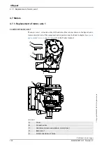
4.7.1. Replacement of motor, axis 1
125
3HAC022031-001 Revision: C
©
Co
py
rig
h
t 200
4-
200
8 ABB. All righ
ts reser
v
ed.
4. Fit the motor by gently lowering it straight down.
Note the position of the motor! Use
the mark , made on the motor base
before removal. See also orientation
of the holes on top of the motor,
shown in the figure
5. Tighten the four
attachment screws and washers
. 4 pcs. TIghtening torque: 2 Nm.
6. In order to release the brakes, connect the 24
VDC power supply to the motor.
Connect power supply to connector
R3.MP1:
•
+ : pin 7
•
- : pin 8
7. Fit the
measuring tool
to the rear of the motor.
Art. no. is specified in
.
Shown in the figure below.
8. Rotate the motor shaft several turns, using the
measuring tool.
There must always be some backlash, meaning
that the shaft should go easy to rotate!
9. Place the tip of a dial indicator against the scribed
mark on the measuring tool.
The tip of the dial indicator must
measure on a 50 mm radius from
the center of the motor shaft.
xx0200000473
A. Measuring tool
10. Set the gear play to 0.02 mm, which corresponds
to a reading on the dial indicator of 0.13 mm.
11. Pull gently in one direction. Note the reading.
(The gear must not turn.)
12. Then gently knock on the tool in the other
direction and note the reading. The difference in
reading = gear play. The gear play should be 0.02
mm which corresponds to a reading on the dial
indicator of 0.13 mm.
13. Tighten the motor attachment screws.
4 pcs. Tightening torque: 23 Nm.
14. Refit the
connection box
with the three
attachment screws and plain washers.
Make sure the gasket is fitted properly!
Shown in the figure
Action
Note/Illustration
Continued
Continues on next page
Содержание IRB 2400/10
Страница 1: ...Product manual Articulated robot IRB 2400 L IRB 2400 10 IRB 2400 16 M2000 M2000A M2004 ...
Страница 2: ......
Страница 8: ...Table of Contents 6 3HAC022031 001 Revision C Copyright 2004 2008 ABB All rights reserved ...
Страница 16: ...Product documentation M2004 3HAC022031 001 Revision C 14 Copyright 2004 2008 ABB All rights reserved ...
Страница 191: ......
Страница 192: ......
Страница 193: ......
Страница 194: ......
Страница 195: ......
Страница 198: ......
Страница 199: ......
Страница 202: ......
Страница 203: ......
Страница 205: ......
Страница 210: ...8 Circuit diagram 8 1 Introduction 3HAC022031 001 Revision C 198 Copyright 2004 2008 ABB All rights reserved Continued ...
Страница 211: ...Manipulator Circuit Diagram 3HAC 6670 3 Rev 01 Product Manual IRB 2400 No of Sheets 13 Sheet no 101 LIST OF CONTENTS ...
Страница 214: ...Manipulator Circuit Diagram 3HAC 6670 3 Rev 01 Product Manual IRB 2400 No of Sheets 13 Sheet no 104 MOTOR AXIS 1 3 ...
Страница 226: ......


