


4 Repair
4.6.2. Replacement of brake release unit
117
3HAC022031-001 Revision: C
©
Co
py
rig
h
t 200
4-
200
8 ABB. All righ
ts reser
v
ed.
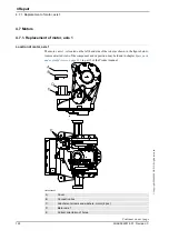
4.6.2. Replacement of brake release unit
Location of brake release unit
The brake release unit is located behind the flange plate at the robot base, as shown below.
xx0200000459
Required equipment
Replacement, brake release unit
The procedure below details how to replace the brake release unit from the robot base.
A
Brake release unit with buttons
Equipment, etc.
Spare part no.
Note
BU w. buttons DSQC 563
3HAC16035-1
Standard toolkit
-
The content is defined in section
Other tools and procedures may
be required. See references to
these procedures in the step-by-
step instructions below.
These procedures include
references to the tools required.
Action
1.
DANGER!
If the robot normally works in an inverted position, it must be removed from this position
and placed on the floor before the work detailed in this procedure may be carried out!
2.
DANGER!
Turn off all electric power, hydraulic and pneumatic pressure supplies to the robot!
3. Remove the cover at the rear of the base.
4. Unscrew the six attachment screws of the brake release unit on the outside of the base.
Continues on next page
Содержание IRB 2400/10
Страница 1: ...Product manual Articulated robot IRB 2400 L IRB 2400 10 IRB 2400 16 M2000 M2000A M2004 ...
Страница 2: ......
Страница 8: ...Table of Contents 6 3HAC022031 001 Revision C Copyright 2004 2008 ABB All rights reserved ...
Страница 16: ...Product documentation M2004 3HAC022031 001 Revision C 14 Copyright 2004 2008 ABB All rights reserved ...
Страница 191: ......
Страница 192: ......
Страница 193: ......
Страница 194: ......
Страница 195: ......
Страница 198: ......
Страница 199: ......
Страница 202: ......
Страница 203: ......
Страница 205: ......
Страница 210: ...8 Circuit diagram 8 1 Introduction 3HAC022031 001 Revision C 198 Copyright 2004 2008 ABB All rights reserved Continued ...
Страница 211: ...Manipulator Circuit Diagram 3HAC 6670 3 Rev 01 Product Manual IRB 2400 No of Sheets 13 Sheet no 101 LIST OF CONTENTS ...
Страница 214: ...Manipulator Circuit Diagram 3HAC 6670 3 Rev 01 Product Manual IRB 2400 No of Sheets 13 Sheet no 104 MOTOR AXIS 1 3 ...
Страница 226: ......


