30 OI/FEP610/FEH610-EN Rev. B |
ProcessMaster FEP610, HygienicMaster FEH610
Sensor
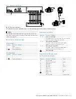
Fig. 43: Connection to sensor in remote mount design (example)
1
Terminals for signal cable
2
Terminal for potential equalization
Change from one to two columns
NOTE
If the O-ring gasket is seated incorrectly or damaged,
this may have an adverse effect on the housing
protection class.
Follow the instructions in chapter "Opening and closing the
terminal box" on page 18 to open and close the housing
safely.
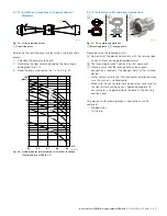
Observe the following points:
— Lead the signal cable into the housing as shown.
— Connect the cables in accordance with the electrical
connection diagram. If present, connect the cable
shielding to the earthing clamp provided.
— Use wire end ferrules when connecting.
— Close unused cable entries using suitable plugs.
G12029
3 S2 E2 E1 S1M1M2
M 20 mm /
NPT 1/2"
PA
2
1
FE


