background image


Installation


CI/FEP300/FEH300-EN 

ProcessMaster / HygienicMaster 

EN - 9 


3 Installation 


3.1 

General information on installation 


The following points must be observed for the installation: 

•  The flow direction must correspond to the identification if present. 

•  The maximum torque for all flange connections must be complied with. 

•  The devices must be installed without mechanical tension (torsion, bending). 

•  Install flange and wafer type units with coplanar counter flanges and use only appropriate 

gaskets. 

•  Use only gaskets made from a compatible material for the fluid and fluid temperatures. 

•  Gaskets must not extend into the flow area since possible turbulence could influence the 

device accuracy. 

•  The pipeline may not exert excessive forces or torques on the device. 

•  Do not remove the plugs in the cable connectors until you are ready to install the electrical 

cable. 

•  Make sure the gaskets for the housing cover are seated properly. Carefully seal the cover. 

Tighten the cover fittings. 

•  A separate transmitter must be installed at a largely vibration-free location. 

•  Do not expose the transmitter and sensor to direct sunlight. Provide appropriate sun 

protection if necessary. 

•  When installing the transmitter in a control cabinet, make sure adequate cooling is provided. 


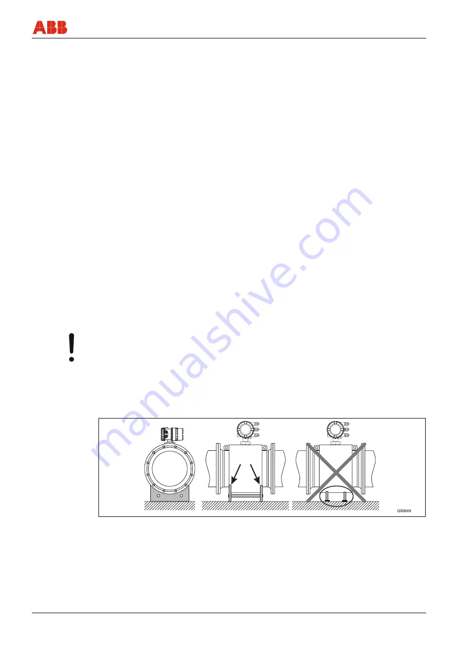
3.1.1  Supports for meter sizes larger than DN 400 


Notice - Potential damage to device!


Improper support for the device may result in deformed housing and damage to internal 
magnet coils.


Place the supports at the edge of the housing (see arrows in the figure).


Devices with meter sizes larger than DN 400 must be mounted with support on a sufficiently 
strong foundation. 


Fig. 3: Support for meter sizes larger than DN 400 


Содержание HART FEH300

Страница 1: ...CI FEP300 FEH300 EN ProcessMaster HygienicMaster Commissioning Instruction Electromagnetic Flowmeter FEP300 FEH300 ...

Страница 2: ......

Страница 3: ...gen Germany Tel 49 551 905 534 Fax 49 551 905 555 CCC support deapr de abb com Copyright 2008 by ABB Automation Products GmbH Subject to change without notice This document is protected by copyright It assists the user with the safe and efficient operation of the device The contents may not be copied or reproduced in whole or in excerpts without prior approval of the copyright holder Contents ...

Страница 4: ...N 400 9 3 1 2 Mounting the measuring tube 10 3 2 Torque information 11 3 2 1 Flanged units ProcessMaster and HygienicMaster 11 3 2 2 Wafer type unit HygienicMaster 13 3 2 3 Variable process connections HygienicMaster 13 3 3 Information on 3A conformity 14 3 4 Installation Requirements 15 3 4 1 Electrode axis 15 3 4 2 In and outlet pipe sections 15 3 4 3 Vertical connections 15 3 4 4 Horizontal con...

Страница 5: ...g the transmitter 24 3 7 1 Connecting the supply power 24 3 7 2 Transmitter 25 3 7 3 Electrical connection diagram 26 4 Startup Operation 28 4 1 Preliminary checks prior to start up 28 4 2 Operation 28 4 2 1 Menu navigation 28 4 2 2 Process display 29 4 3 Commissioning the unit 30 4 3 1 Downloading the system data 30 4 3 2 Parametrizing via the Easy Set up menu function 31 4 3 3 Changing to the in...

Страница 6: ...n enables the optimal protection of personnel as well as the environment from hazards and the safe and trouble free operation of the device 1 2 Symbols and warnings Danger Serious damage to health risk to life One of these symbols in conjunction with the Danger warning indicates an imminent danger If it is not avoided death or serious injury will result Warning Bodily injury The symbol in conjunct...

Страница 7: ...t for external loads e g as a support for pipes etc Material gain e g by painting over the name plate or adding parts by welding soldering Material loss e g by drilling the housing 1 5 Technical limit values The device is designed for use exclusively within the stated values on the name plate and within the technical limit values specified in the data sheets The following technical limit values mu...

Страница 8: ...rify the resistance of all parts that come into contact with the fluid to be measured ABB will gladly support you with the selection however cannot accept any liability The operators must strictly observe the applicable national regulations in their countries with regards to installation function tests repairs and maintenance of electrical devices 1 8 Personnel qualification The installation commi...

Страница 9: ...power must be installed according to the relevant national and international standards A separate fuse must be connected upstream and in close proximity to each unit The fuses must be identified accordingly The unit has a protection class of I and overvoltage class II IEC664 The power supply and the electrical circuit for the coils of the sensor are dangerous and pose a contact risk The coils and ...

Страница 10: ...ly during transport Support the meter laterally For transport of flanged units smaller than DN 450 use a lifting strap Wrap the straps around both process connections when lifting the device Avoid chains since these may damage the housing Fig 1 Transport of flanged units smaller than DN 450 2 3 Transport of flanged units larger than DN 400 Notice Potential damage to device Use of a forklift to tra...

Страница 11: ... torques on the device Do not remove the plugs in the cable connectors until you are ready to install the electrical cable Make sure the gaskets for the housing cover are seated properly Carefully seal the cover Tighten the cover fittings A separate transmitter must be installed at a largely vibration free location Do not expose the transmitter and sensor to direct sunlight Provide appropriate sun...

Страница 12: ...sent to the right and left of the measuring tube To prevent possible leakage make sure that the liner on the flange is not cut or damaged 2 Position the measuring tube coplanar and centered between the pipes 3 Install gaskets between the surfaces Important For best results make sure the flowmeter sensor gaskets fit concentrically with the measuring tube 4 Use the appropriate bolts for the flanges ...

Страница 13: ...18 40 4 x M16 34 CL 150 4 x M12 15 32 1 1 4 CL 300 4 x M16 27 40 4 x M16 43 CL 150 4 x M12 20 40 1 1 2 CL 300 4 x M20 43 40 4 x M16 56 CL 150 4 x M16 39 50 2 CL 300 8 x M16 28 16 4 x M16 34 40 8 x M16 39 CL 150 4 x M16 49 65 2 1 2 CL 300 8 x M20 43 40 8 x M16 49 CL 150 4 x M16 69 80 3 CL 300 8 x M20 62 16 8 x M16 47 40 8 x M20 77 CL 150 8 x M16 49 100 4 CL 300 8 x M20 92 16 8 x M16 62 40 8 x M24 1...

Страница 14: ...x M27 185 10 12 x M20 115 16 12 x M24 160 25 16 x M27 175 40 16 x M30 340 CL 150 12 x M24 180 300 12 CL 300 16 x M30 265 10 16 x M20 145 16 16 x M24 195 350 14 25 16 x M30 280 10 16 x M24 200 16 16 x M27 250 400 16 25 16 x M33 365 500 20 10 20 x M24 200 600 24 10 20 x M27 260 700 28 10 24 x M27 300 800 32 10 24 x M30 390 900 36 10 28 x M30 385 1000 40 10 28 x M33 480 1 Connection flange DIN EN1092...

Страница 15: ...15 CL 150 4 x M12 upon request 25 1 CL 300 4 x M16 upon request 40 4 x M16 26 CL 150 4 x M12 upon request 32 1 1 4 CL 300 4 x M20 upon request 40 4 x M16 33 CL 150 4 x M12 upon request 40 1 1 2 CL 300 4 x M20 upon request 40 4 x M16 46 CL 150 4 x M16 upon request 50 2 CL 300 8 x M16 upon request 16 8 x M16 30 65 2 1 2 CL 150 4 x M16 upon request 16 8 x M16 40 80 3 CL 150 4 x M16 upon request 16 8 ...

Страница 16: ...e may not be installed vertically with the terminal box or transmitter housing pointing downward Fig 5 The bracket mounting option no longer applies Fig 6 1 Bracket Please ensure that the leakage hole of the process connection is located at the deepest point of the installed device 1 G00169 Fig 7 1 Leakage hole ...

Страница 17: ...be installed in the outlet pipe section 2 For compliance with the measuring accuracy observe the inlet and outlet pipe sections G00037 1 2 3xDN 2xDN Fig 10 3 4 3 Vertical connections Vertical installation for measurement of abrasive fluids flow preferably from below to above Fig 11 3 4 4 Horizontal connections Meter tube must always be completely full Provide for a slight incline of the connection...

Страница 18: ...be insulated after installing the unit according to the following illustration Fig 16 1 Insulation 3 4 9 Installation in pipelines with larger nominal diameters Determine the resulting pressure loss when using reduction pieces 1 1 Calculate the diameter ratio d D 2 Determine the flow velocity based on the flow range nomograph Fig 18 3 Read the pressure drop on the Y axis in Fig 18 Fig 17 1 d V Δp ...

Страница 19: ...ld be identical An additional ground on the terminals is not required Important If the flowmeter is installed in plastic or earthenware pipelines or in pipelines with an insulating lining transient current may flow through the grounding electrode in special cases In the long term this may destroy the sensor since the ground electrode will in turn degrade electrochemically In these special cases th...

Страница 20: ...iner For plastic pipes or pipes with insulating lining the ground is provided by the grounding plate as shown in the figure below or via grounding electrodes that must be installed in the device option If grounding electrodes are used the grounding plate is not necessary 1 Install the flowmeter sensor with grounding plate 3 in the pipeline 2 Connect the terminal plug 2 for the grounding plate 3 an...

Страница 21: ...nt This element grounds the measuring fluid 3 5 7 Ground for devices with protective plates The protective plates are used to protect the edges of the liner in the measuring tube e g for abrasive fluids In addition they function as a grounding plate For plastic or pipes with insulating lining electrically connect the protective plate in the same manner as a grounding plate 3 5 8 Ground with conduc...

Страница 22: ...l other wires The shields may not touch signal short circuit Fig 23 Sensor side dimensions in mm inch Fig 24 Transmitter side dimensions in mm inch L1 max stripped length 105 4 10 1 Measurement potential 3 green L2 70 2 76 2 Signal line E1 violet L2 60 2 36 3 Shield 1S L2 60 2 36 4 Shield 2S L2 60 2 36 5 Signal line E2 blue L2 60 2 36 6 Data line D2 yellow L2 70 2 76 7 Data line D1 orange L2 70 2 ...

Страница 23: ...fier and 200 m 656 ft with pre amplifier Avoid routing the cable in the vicinity of electrical equipment or switching elements that can create stray fields switching pulses and induction If this is not possible run the signal magnet coil cable through a metal pipe and connect this to the station ground All leads must be shielded and connected to earth ground To shield against magnetic interference...

Страница 24: ...the terminal box of the sensor 3 Route the cable from the terminal box to above the maximum flooding height of 5 m 16 4 ft 4 Tighten the cable gland 5 Carefully seal the terminal box Make sure the gaskets for the cover are seated properly Notice Potentially adverse effect on IP 68 protection class The sensor s IP 68 protection class may be compromised by damage to the signal cable The sheathing of...

Страница 25: ...ling activities in order avoid moisture penetration Before starting check all the connections for correct fitting and stability Do not overfill the terminal box Keep the sealing compound away from the O ring and the seal groove see fig Fig 27 Prevent the sealing compound from penetrating a thermowell if an NPT thread is used Procedure 1 Cut open the protective enclosure of the sealing compound see...

Страница 26: ... comply with IEC 227 or IEC 245 Connect a switch or a line switch in the supply power feed to the transmitter This switch should be located near the transmitter and marked as being associated with the device The transmitter and the flowmeter sensor have to be connected to a functional ground Important Observe the limit values for the supply power provided in the data sheet and operating instructio...

Страница 27: ...res function as a driven shield to transmit the measurement signal The cable is attached to the sensor and transmitter according to the connection diagram Fig 29 1 Terminal cover 2 Busbar SE 3 Clip 4 Signal and magnet coil cable Important The power supply for the optional pre amplifier is provided via terminals 1S and 2S The transmitter automatically detects the sensor and switches to the required...

Страница 28: ... width 0 1 2000 ms The pulse factor and the pulse width are interdependent and are calculated dynamically Configuration as contact output Function System alarm empty pipe alarm max min alarm flow direction signaling other Configuration as active output U 19 21 V Imax 220 mA fmax 5250 Hz Configuration as passive output Umax 30 V Imax 220 mA fmax 5250 Hz 4 Digital input Terminals 81 82 contact input...

Страница 29: ...internal E external Fig 31 Digital output DO1 Max allowable load RB depending on source voltage U A Active configuration B Passive configuration I internal E external permissible range Fig 32 Digital output DO2 e g for system monitoring Max Min alarm for empty pipe or forward reverse signal or counting pulses function configurable by software Digital output DO1 and DO2 separate forward and reverse...

Страница 30: ...housing cover must be sealed before switching on the supply power 4 2 Operation 4 2 1 Menu navigation M00024 4 3 2 1 Fig 35 The 1 4 2 and 3 buttons are available for the menu controlled configuration The menu submenu name is displayed above in the LCD display The number line of the currently selected menu item is displayed in the upper right of the LCD display A scroll bar is located on the right ...

Страница 31: ...e using both or buttons The button selects the desired menu item 4 2 2 Process display The process display appears after switching on the unit Q Current flowrate Totalizer value for forward flow direction Totalizer value for reverse flow direction The meter location is displayed on the upper left for example Boiler 9 The meter location can be entered in the menu Device Setup Sensor Meter Location ...

Страница 32: ...key This downloads the calibration data for the sensor and the transmitter settings from the sensor memory an integral memory module to the transmitter After replacing the sensor Select Sensor by pressing the key This downloads the calibration data for the sensor and the transmitter settings from the sensor memory an integral memory module to the transmitter The settings for the transmitter are st...

Страница 33: ...lse width damping status of current output during alarm Iout at Alarm Iout Low Alarm Iout High Alarm The following section describes parametrization via the Easy Set up menu function Press the key to change to the setup level of the process display Use the keys to select the Standard menu item In the password menu select ok key There is no factory default password Select ok key to switch to the co...

Страница 34: ...s per unit are output The relevant settings are provided in the next menu Frequency mode In the frequency mode a frequency proportional to the flowrate is output The maximum frequency corresponding to the mass flow range is configurable The factory default is pulse mode Press the key and set the pulses per unit for the pulse output After entering the settings press the key to move to the next menu...

Страница 35: ...ge 21 23 mA Factory setting 21 8 mA Press the to set the system zero Valve must be closed The sensor must be filled completely The fluid must be at standstill Press OK to start the automatic adjust Once you have set all the parameters you return to the Easy Set up menu The most important parameters are now set Press the key to Exit and return to the process display Important For additional informa...

Страница 36: ... current output is 4 20 mA active Digital output DO1 terminals 51 52 Digital output DO1 is preconfigured as a passive pulse output factory default Empty pipe detection Empty pipe detection is deactivated factory default 4 3 3 Changing to the information level Press the key to change to the information level of the process display Use the keys to select the desired information The Diagnostics menu ...

Страница 37: ...gal min 1080 m3 h 4755 US gal min 250 10 36 m3 h 159 US gal min 1800 m3 h 7925 US gal min 300 12 48 m3 h 211 US gal min 2400 m3 h 10567 US gal min 350 14 66 m3 h 291 US gal min 3300 m3 h 14529 US gal min 400 16 90 m3 h 396 US gal min 4500 m3 h 19813 US gal min 450 18 120 m3 h 528 US gal min 6000 m3 h 26417 US gal min 500 20 132 m3 h 581 US gal min 6600 m3 h 29059 US gal min 600 24 192 m3 h 845 US ...

Страница 38: ...0 5 2 Permits and certifications Zu Icon Description CE mark By placing the CE mark on the name plate ABB Automation Products GmbH declares its conformance with the following directives EMC directive 2004 108 EC Low voltage directive 2006 95 EC Pressure equipment directive PED 97 23 EC Important All documentation declarations of conformity and certificates are available in the download area of ABB...

Страница 39: ...Appendix CI FEP300 FEH300 EN ProcessMaster HygienicMaster EN 37 ...

Страница 40: ...Appendix 38 EN ProcessMaster HygienicMaster CI FEP300 FEH300 EN ...

Страница 41: ......

Страница 42: ... notice Printed in the Fed Rep of Germany 08 2008 ABB 2008 3KXF231300R4401 CI FEP300 FEH300 EN ABB Limited Oldends Lane Stonehouse Gloucestershire GL10 3TA UK Tel 44 0 1453 826661 Fax 44 0 1453 829671 ABB Inc 125 E County Line Road Warminster PA 18974 USA Tel 1 215 674 6000 Fax 1 215 674 7183 ABB Automation Products GmbH Dransfelder Str 2 37079 Goettingen Germany Tel 49 551 905 534 Fax 49 551 905 ...

Отзывы: